Week 2:- BiW Fixture Basics Challenge
AUTOMOTIVE BIW FIXTURE DESIGN USING CATIA V5
Q.1)
PROJECT EXECUTION ACTIVITY
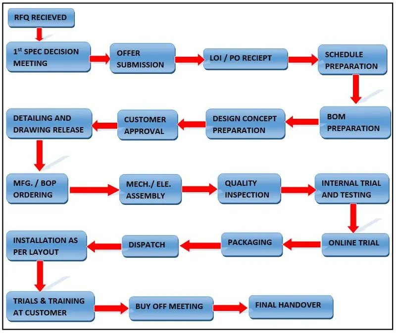
- RFQ RECIVED
Receival of RFQ from the customer is the first stage in the project execution activity. customer specifies his requirements, specifications etc. in form of documents or
data in the RFQ. Based on the received RFQ, supplier has to create Technical and Commercial offer.
- 1st SPEC DECISION MEETING
Supplier and the Buyer have their 1st spec. decision meeting, for knowing the scope of work, meeting of technical requirement, timeline for product delivery and commercial terms and conditions.
- OFFER SUBMISSION
Once the 1st spec. decision meeting is finished, the offer is prepared and submitted to customer for scrutiny. The offer consists of both technical and commercial offer.
- LOI / PO RECEIPT
Based on the submitted offer, customer reviews our technical and commercial offer. Customer first checks whether the offer has been submitted conforming to the technical specifications or not. If any discrepancies found, customer raises queries. Supplier has to clarify all the technical points in order to get technically cleared.
After the clearance of technical offer. Customer negotiates with the supplier in terms of cost and payment conditions. Once commercial offer is cleared. Supplier receives LOI / PO receipt for order booking.
- SCHEDULE PREPARATION
On receival of the PO the project kick-off start takes place. The timeline is fixed so there should be plan to beat the deadline & to complete the project. The time required to finish the individual activity is calculated. By calculating all the timelines. the total time required is calculated.
Based on the calculated timeline, the master schedule is created, which illustrates, how the project will be started and reaches its finish line.
- BOM PREPARATION
The complete Bill of Material is generated in the system for the sub-assemblies of the product. Without proper BOM, the end product may fail to achieve its functioning condition.
- DESIGN CONCEPT PREPARATION
Further step is to design the concept as per the BOM. The design should be same as per the offer submitted during pre-bid stage. The Drawings in 2D and 3D Model should be submitted to the customer for approval.
- CUSTOMER APPROVAL
Once the customer receives the related design documents from the supplier, complete reviewing of the designed concept is made, in order to match with the requirement.
After the drawings and designed models are checked, customer provides clearance to proceed for Manufacturing of the product to the supplier.
- DETAILING AND DRAWING RELEASE
After the clearance of Design concept and Drawings from customer, the supplier releases the same drawings to the production shop floor for manufacturing the product.
- MANUFACTURING / BOP ORDERING
Manufacturing department will receive the drawings to start manufacturing of items as per the BOM. The purchase team will place order for B/O parts like motor, gearbox, cylinder & valves.
Once the material gets ready, QC team should inspect all part received is as per specification or not.
- / ELE. ASSEMBLY
The manufactured parts are assembled in the assembly department, complying to the BOM. The Mechanical and Electrical assembly is completed, accordingly with the help of respective assembly tools.
- QUALITY INSPECTION
Once the assembly is completed. The Quality control team inspects the sub-parts in its assembled condition.
If any deviation / changes found with respect to the design / material / manufacturing, then queries are raised by quality team with the respective department.
- INTERNAL TRIAL AND TESTING / ONLINE TRIAL
The Final assembled product is taken to the testing department, to carry out the respective tests.
The testing will be related to both mechanical and electrical functioning of the product. Some tests like endurance and fatigue test, will let us know how the product gets failed during longer period of times.
- PACKAGING & DISPATCH
The sub-assemblies / sub-parts are packed in standard procedure. As during transit, the product may get damaged, hence the proper packaging is very important. Once the packaging is done the product is ready to get dispatched to the customer destination.
- INSTALLATION AS PER LAYOUT
Once the product is received by the Buyer, the installation of the product as to be done by the supplier end.
The dis-assembled parts have to be re-assembled and installed successfully, as per the customer’s request.
- TRIALS & TRAINING AT CUSTOMER
After successful supervision and installation of the product, customer requests supplier to run the trials.
Complete training has to be provided to the customer, to know how the product operates and how to handle the situation, when they come across any problem.
Training and Instruction Manual has to be handed over to the customer.
- BUY OFF MEETING
Once training is completed there will be buy off meeting between customer & project team with discussion, if there is any additional requirement has to be incorporated.
Then customer will raise queries or asks for certain modification to be done, which is completed timely.
- FINAL HANDOVER
Finally supplier handovers the product to the customer, and relieves the formalities and paper work.
Future sales and service are provided to the customer by the supplier to make the product run smoothly.
Q.2)
TYPES OF JOINING PROCESS
Joining Process
Assembly is an important step for manufacturing solid products, especially when the shape of the product is complicated having multifarious geometrical features. It is neither feasible nor economical all the times to directly produce a product having intricate shape.
In such scenario, making small simple parts and joining them together is the best possible way. Joining consists of a large number of processes used to assemble two or more parts together, irrespective of their composition, properties, features, shapes, etc.
By definition, joining is one of the manufacturing processes by which two or more materials can be permanently or temporarily joined or assembled together with or without the application of external element in order to form a single unit.
Some of the commonly used joining processes are enlisted below,
- Welding
- Soldering
- Brazing
- Fasteners (including nut-bolt, nail, hook, clip, clutch, button, zipper, etc.)
- Adhesive bonding
- Resin bonding
- Cotter joint
- Knuckle joint, etc.
WELDING PROCESS
Welding is one of the manufacturing processes by which two or more similar or dissimilar materials can be joined permanently by coalescence formation with or without the applications of external pressure, heat or filler material.
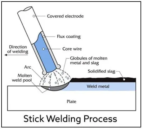
There are two categories of welding processes
Fusion welding - coalescence is accomplished by melting the two parts to be joined, in some cases adding filler metal to the joint.
Examples: arc welding, resistance spot welding, oxyfuel gas welding
Solid state welding - heat and/or pressure are used to achieve coalescence, but no melting of base metals occurs and no filler metal is added
Examples: forge welding, diffusion welding, friction welding
SOLDERING PROCESS
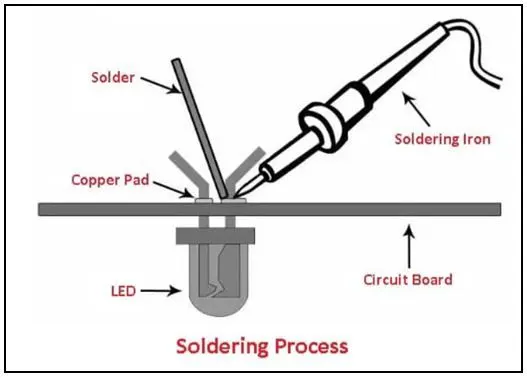
Soldering is a process used for joining metal parts to form a mechanical or electrical bond. It typically uses a low melting point metal alloy (solder) which is melted and applied to the metal parts to be joined and this bonds to the metal parts and forms a connection when the solder solidifies.
It is different to welding in that the parts being joined are not melted and are usually not the same material as the solder.
Types of Soldering Process
- Soft Soldering
It is used in sheet-metal work for joining parts that are not exposed to high temperatures and are not subjected to extreme loads and forces. Soft soldering is also used for joining wires and small components.
The solder, which is mostly composed of lead and tin, has a melting range of 150 to 350°C. A suitable flux is always used in soft soldering.
Its function is to prevent oxidation of the surfaces to be soldered or to dissolve oxides that settled on the metal surfaces during the healing process. Although corrosive, Zinc chloride is the most common soldering flux.
The soft soldering has the lowest filler metal melting point of all soldering types, which is less than about 400°C, these filler metals are typically alloys, often with liquid temperatures below 350°C.
Due to the low temperatures used in soft soldering, it thermally stresses components the least, but does not create strong joints and is therefore unsuitable for mechanical load-bearing applications.
2.) Hard or Silver Soldering
It employs solder which metal at higher temperatures and are stronger than those used in soft soldering. Silver soldering is a hard soldering method, and silver mixed with tin is utilised as a solder.
The temperatures of the various hard solder vary from about 600 to 900°. The fluxes are mostly in paste form and are applied to the joint with a brush before heating. In hard soldering, a blowtorch constitutes the equipment.
The different compositions of solder for different purposes are as follows:
- Soft solder-lead 37%, tin 63%.
- Medium solder-lead 50%, tin%.
- Plumber’s solder-lead 70%, tin 30%.
- Electrician’s solder-lead 58%, tin 42%.
BRAZING PROCESS
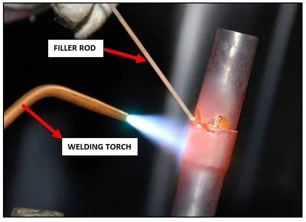
In brazing joining of metal pieces is done with the help of filler metal. Filler metal is melted and distributed by capillary action between the faying surfaces of the metallic parts being joined. In this case only filler metal melts. There is no melting of workpiece metal.
The filler metal (brazing metal) should have the melting point more than 450°C. Its melting point should be lesser than the melting point of workpiece metal. The metallurgical bonding between work and filler metal and geometric constrictions imposed on the joint by the workpiece metal make the joint stronger than the filler metal out of which the joint has been formed.
Types of Brazing Process:-
- Torch Brazing
In case of torch brazing, flux is applied to the part surfaces and a torch is used to focus flame against the work at the joint. A reducing flame is used to prevent the oxidation. Filler metal wire or rod is added to the joint. Torch uses mixture of two gases, oxygen and acetylene, as a fuel like gas welding.
- Furnace Brazing
In this case, furnace is used to heat the workpieces to be joined by brazing operation. In medium production, usually in batches, the component parts and brazing metal are loaded into a furnace, heated to brazing temperature, and then cooled and removed. If high production rate is required all the parts and brazing material are loaded on a conveyer to pass through then into a furnace. A neutral or reducing atmosphere is desired to make a good quality joint.
- Induction Brazing
Induction brazing uses electrical resistance of workpiece and high frequency current induced into the same as a source of heat generation. The parts are pre-loaded with filler metal and placed in a high frequency AC field. Frequencies ranging from 5 to 5000 kHz is used. High frequency power source provides surface heating, however, low frequency causes deeper heating into the workpieces. Low frequency current is recommended for heavier and big sections (workpieces). Any production rate, low to high, can be achieved by this process.
- Resistance Brazing
In case of resistance welding the workpieces are directly connected to electrical rather than induction of electric current line induction brazing. Heat to melt the filler metal is obtained by resistance to flow of electric current through the joint to be made. Equipment for resistance brazing is same that is used for resistance welding, only lower power ratings are used in this case. Filler metal into the joint is placed between the electrode before passing current through them. Rapid heating cycles can be achieved in resistance welding. It is recommended to make smaller joints.
- Dip Brazing
In this case heating of the joint is done by immersing it into the molten soft bath or molten metal bath. In case of salt bath method, filler metal is pre-loaded to the joint and flux is contained in to the hot salt bath. The filler metal melts into the joint when it is submerged into the hot bath. Its solidification and formation of the joint takes place after taking out the workpiece from the bath. In case of metal bath method, the bath contains molten filler metal. The joint is applied with flux and dipped to the bath. Molten filler metal, fills the joint through capillary action. The joint forms after its solidification after taking it out from molten metal bath. Fast heating is possible in this case. It is recommended for making multiple joints in a single workpiece or joining multiple pairs of workpieces simultaneously.
- Infrared Brazing
It uses infrared lamps. These lamps are capable of focused heating of very thin sections. They can generate upto 5000 watts of radiant heat energy. The generated heat is focused at the joint for brazing which are pre-loaded with filler metal and flux. The process is recommended and limited to join very thin sections.
Q.3)
RESISTANCE WELDING
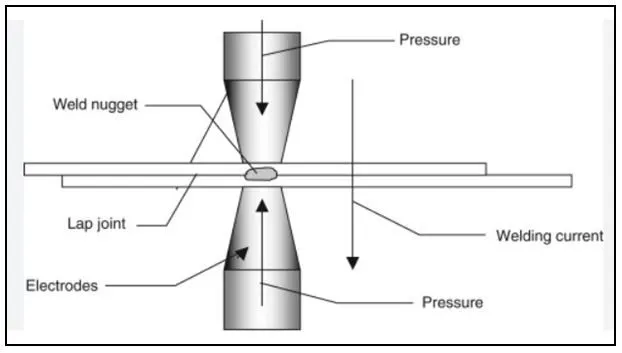
Resistance Welding is a welding process, in which work pieces are welded due to a combination of a pressure applied to them and a localized heat generated by a high electric current flowing through the contact area of the weld.
Resistance Welding Processes and Equipments - Resistance welding is a group of welding processes wherein coalescence is produced by the heat obtained from resistance of the work to the flow of electric current in a circuit of which the work is a part and by the applications of pressure. No filler metal is needed.
Heat produced by the current is sufficient for local melting of the work piece at the contact point and formation of small weld pool (“nugget”). The molten metal is then solidifies under a pressure and joins the pieces. Time of the process and values of the pressure and flowing current, required for formation of reliable joint, are determined by dimensions of the electrodes and the work piece metal type.
AC electric current (up to 100 000 A) is supplied through copper electrodes connected to the secondary coil of a welding transformer.
The following metals may be welded by Resistance Welding:
- Low carbon steels - the widest application of Resistance Welding Aluminum alloys
- Medium carbon steels, high carbon steels and Alloy steels (may be welded, but the weld is brittle)
Advantages of Resistance Welding -
(i) Fast rate of production.
(ii) No filler rod is needed.
(iii) Semi-automatic equipments.
(iv) Less skilled workers can do the job.
(v) Both similar and dissimilar metals can be welded.
(vi) High reliability and reproducibility are obtained.
(vii) More general elimination of warping or distortion of parts.
Disadvantages of Resistance Welding –
(i) The initial cost of equipment is high.
(ii) Skilled persons are needed for the maintenance of equipment and its controls.
(iii) In some materials, special surface preparation is required.
(iv) Bigger job thicknesses cannot be welded.
The most popular methods of Resistance Welding are:
- Spot Welding (RSW)
- Projection welding (PW)
- Seam Welding (RSEW)
SPOT WELDING
Spot welding is a resistance welding process in which overlapping sheets are joined by local fusion at one or more spots by the heat generated, by resistance to the flow of electric current through workpieces that are held together under force by two electrodes, one above and the other below the two overlapping sheets.
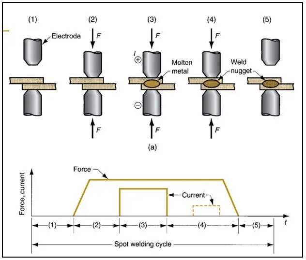
Resistance spot welding is a process in which faying surfaces are joined in one or more spots by resistance to the flow of electric current through workpieces that are held together under force by electrodes.
The contacting surfaces in the region of current concentration are heated by a short-time pulse of low-voltage, high-amperage current to form a fused nugget of weld metal. When the flow of current ceases, the electrode force is maintained while the weld metal rapidly cools and solidifies.
The electrodes are retracted after each weld, which usually is completed in a fraction of a second.
PROJECTION WELDING
In the projection welding, as per the name, different projections are formed for effective welding. Projection Welding is one of the types of resistance welding and its working principle is quite the same as the resistance welding. The only difference here is that projection or embossed.
Working Principle
As per the definition, different projections are formed in this welding technique. Here, the metal pieces that are to be joined are kept in between the two electrodes. A larger pressure force is applied to the electrodes. As current is passed through the system, the heat formation takes place due to the internal resistance of the metal workpieces.
One point that you must note down here, is that the heat generation takes place due to the internal resistance of the metal workpieces rather than an electric arc. Those projections concentrate the heat. As the pressure applied to the electrodes increases, this projection collapses and the formation of the fused weld nugget takes place. Thus, a quality weld is formed joints are used for the welding purpose.
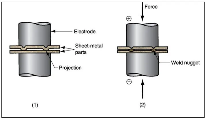
As per the above diagram,
(1) Start of operation, contact between parts is at projections;
(2) when current is applied, weld nuggets similar to spotwelding are formed at the projections
Application
As Projection welding is mostly used for the mass production. It has many applications such as:
Automobile industry uses projection welding to a very large extent.
This welding process is also used for the fan covers and hollow metal doors.
It is also used for producing the compressor parts and for the semi-conductors.
RESISTANCE-SEAM WELDING (RSEW)
Seam Welding is a Resistance Welding (RW) process of continuous joining of overlapping sheets by passing them between two rotating electrode wheels. Heat generated by the electric current flowing through the contact area and pressure provided by the wheels are sufficient to produce a leak-tight weld.
Resistance seam welding (RSEW) is a resistance welding process which produces coalescence at the faying surfaces the heat obtained from resistance to electric current through the work parts held together under pressure by electrodes.
Working Principle
The resulting weld is a series of overlapping resistance spot welds made progressively along a joint rotating the electrodes. When the spots are not overlapped enough to produce gaslight welds it is a variation known as roll resistance spot welding. This process differs from spot welding since the electrodes are wheels. Both the upper and lower electrode wheels are powered. Pressure is applied in the same manner as a press type welder.
The wheels can be either in line with the throat of the machine or transverse. If they are in line, it is normally called a longitudinal seam welding machine. Welding current is transferred through the bearing of the roller electrode wheels. Water cooling is not provided internally and therefore the weld area is flooded with cooling water to keep the electrode wheels cool.
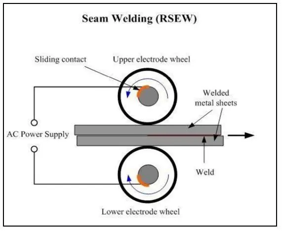
In seam welding a rather complex control system is required. This involves the travel speed as well as the sequence of current flow to provide for overlapping welds. The welding speed, the spots per inch, and the timing schedule are dependent on each other. Welding schedules provide the pressure, the current, the speed, and the size of the electrode wheels.
This process is quite common for making flange welds, for making watertight joints for tanks, etc. Another variation is the so-called mash seam welding where the lap is fairly narrow and the electrode wheel is at least twice as wide as used for standard seam welding. The pressure is increased to approximately 300 times normal pressure. The final weld mash seam thickness is only 25% greater than the original single sheet.
Applications of RSEW
- Girth weld is possible in rectangular or square or even in circular shapes.
- Most of the metals can be welded (Except copper and some high percentage copper alloys) o
- Butt welding can be done.
Resistance welding in Automobile Industry
Resistance welding is an important process in the automotive industry. The advantages of resistance welding are many: an economical process, adaptable to a wide variety of materials (including low carbon steel, coated steels, stainless steel, aluminum, nickel, titanium, and copper alloys) and thicknesses, a process with short cycle times, and overall, a relatively robust process with some tolerance to fit-up variations.
Resistance Spot Welding (often just called spot welding) is a cost-effective joining technology that continues to be very popular in the automotive industry where high reproducibility and automation are essential criteria. An additional advantage is that, with a suitable choice of parameters, a high quality of joints can be obtained without being dependent on a welder’s ability.
Q.4)
FUSION WELDING
Fusion welding is a process that uses heat to join or fuse two or more materials by heating them to melting point. The process may or may not require the use a filler material. External application of pressure is not required for fusion welding processes, except for resistance welding, where substantial contact pressure is required during welding for sound joining.
Fusion welding is of greatest importance in the fabrication of engineering structures. There are many ways in which fusion welding can be carried out, but all of them involve the deposition of a small amount of molten steel between the components to be joined or coated. When the steel solidifies, it welds the components together.
The metallurgy of the welded joint can be categorised into two major regions, the fusion zone and the heat-affected zone (HAZ). The fusion zone represents both the deposited metal and the parts of the steel component melted during the process, and is a solidification microstructure.
The HAZ, on the other hand, represents those regions in the close proximity of the weld, where the heat input during welding changes the microstructure without melting the steel. This chapter describes the development of microstructure in both zones, beginning with the fused regions. Virtually every aspect of phase transformation in steels is relevant to the subject of welding. There is an opportunity for a whole series of transformations to occur successively as the weld cools from the liquid state.
Types of Fusion Welding are:
- Shielded Metal Arc Welding.
- Metal Inert Gas Welding.
- Gas- shielded tungsten arc welding or TIG.
- Plasma Arc Welding.
- Submerged Arc Welding.
SHIELDED METAL ARC WELDING.
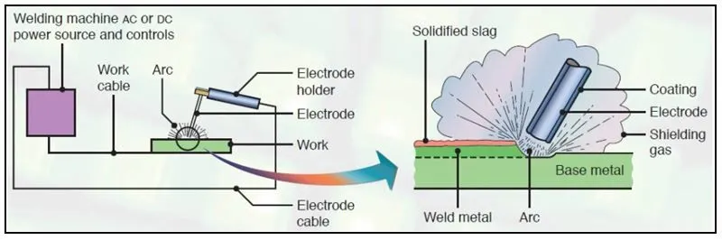
Shielded Metal Arc Welding (SMAW) or Stick welding is a process which melts and joins metals by heating them with an arc between a coated metal electrode and the workpiece. The electrode outer coating, called flux, assists in creating the arc and provides the shielding gas and slag covering to protect the weld from contamination.
The electrode core provides most of the weld filler metal. When the electrode is moved along the workpiece at the correct speed the metal deposits in a uniform layer called a bead. The Stick welding power source provides constant current (CC) and may be either alternating current (AC) or direct current (DC), depending on the electrode being used.
The best welding characteristics are usually obtained using DC power sources. The power in a welding circuit is measured in voltage and current. The voltage (Volts) is governed by the arc length between the electrode and the workpiece and is influenced by electrode diameter. Current is a more practical measure of the power in a weld circuit and is measured in amperes (Amps).
METAL INERT GAS WELDING
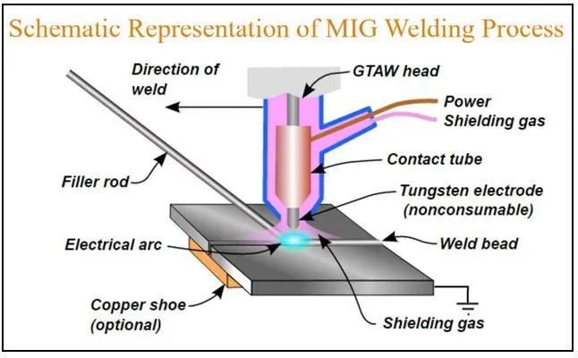
Metal Inert Gas Welding (Gas Metal Arc Welding) is a arc welding process, in which the weld is shielded by an external gas (Argon, helium, CO2, argon + Oxygen or other gas mixtures).
Consumable electrode wire, having chemical composition similar to that of the parent material, is continuously fed from a spool to the arc zone. The arc heats and melts both the work pieces edges and the electrode wire. The fused electrode material is supplied to the surfaces of the work pieces, fills the weld pool and forms joint.
Due to automatic feeding of the filling wire (electrode) the process is referred to as a semi-automatic. The operator controls only the torch positioning and speed.
MIG also known as gas metal arc welding (GMAW) is the most common industrial welding process, preferred for its versatility, speed and the relative ease of adapting the process even to robotic automation. It is used extensively by the sheet metal industry and by extension, the automobile industry.
GAS- SHIELDED TUNGSTEN ARC WELDING OR TIG
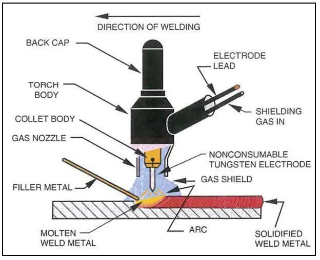
Gas Tungsten Arc Welding (GTAW) also called Tungsten Inert Gas (TIG) Tungsten electrode heats the metal that the welder is welding and gas (which is usually Argon) protects the weld from pollutants carried with air.
TIG welding uses a hand-added, non-consumable Tungsten Filler tool. A constant-current welding power supply produces energy which is generated by a column of strongly ionized gas and metal vapours known as plasma through the arc.
GTAW is commonly used to weld thin sections of non-ferrous and stainless steel metals like aluminium, magnesium and copper alloys.
Gas Tungsten Arc Welding (GTAW) or TIG is most widely used for welding stainless steel and non-ferrous materials such as aluminium and magnesium but can be applied to almost all metals, with a notable exception being zinc and its alloys.
The carbon steel applications are limited not because of process constraints, but due to the presence of more economical steel welding methods, such as gas arc welding and metal arc welding shielding. In addition, GTAW can be carried out in a range of other than flat positions, depending on the welder's skill and the welded materials.
PLASMA ARC WELDING
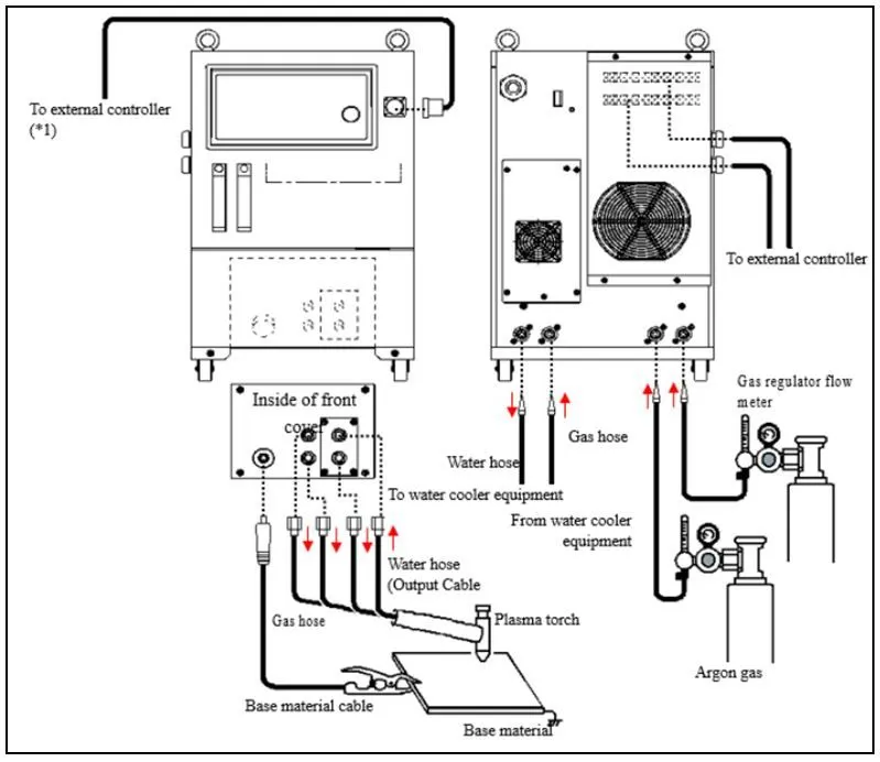
Plasma Arc Welding (PAW) is an arc welding process that employs a high temperature, constricted plasma gas column to obtain the melting and coalescence of most metals. This column of plasma is constricted by an orifice placed downstream of the electrode.
A typical plasma welding system consists of a pilot arc control console, a DC power supply with a suitable welding range, a plasma welding torch (manual or mechanized) and a closed loop coolant recirculator.
PILOT ARC CONTROL CONSOLE - The control console is the 'mixing box' into which the power, gases and coolant are controlled and monitored. It also contains a small DC power supply for the pilot arc. Some control consoles provide additional controls and meters to assist in weld parameter control.
POWER SUPPLY - Plasma arc welding is done with the use of straight polarity (DCEN) or VP (Variable Polarity) power source. The use of a DC power supply is recommended for the welding of ferrous metals. Were a VP power supply is recommended for the welding of non-ferrous metals such as aluminum or aluminum alloys. A typical DC or VP power supply with constant-current characteristics, remote contactor/current control, and suitable welding range is recommended for most operations. A solid-state power supply with a non-mechanical contactor is recommended when performing high duty cycle short duration welds. A sequence programmer, consisting of current or gas slope (taper), pulse, and weld time is required for many automated welding applications.
TORCH - A plasma welding torch suitable for the particular welding operation should be used. Torches are available with various head and size configurations. Most are liquid cooled. The orifices of some torches are also liquid cooled to provide improved orifice life and higher current carrying capacity. Most torches are designed with an orifice that is inserted into a water jacket. These torches cannot operate at the higher (above 250 amps) current levels but do allow the “changing out” of the orifice without disturbing a water seal. Plasma torches use tungsten electrodes, which are normally 2% thoriated. The diameter varies with the current. Lower current levels (below 150 amps) require smaller electrode diameters (3/32', 2.4 mm) and higher current or high duty cycles require larger electrodes (3/16', 4.8 mm) to withstand the heat loads.
COOLANT RECIRCULATOR - A coolant recirculator of a nonferrous design must be used. The use of deionized water to prevent the establishment of electrolysis in the torch is required.
SUBMERGED ARC WELDING
Submerged arc welding is most efficient if the joint can be filled with as few passes as possible. If, when working in mild steel, the workpiece can be turned over, and if the material is not too thick, a bead is often applied from each side of the joint. If the basic material is alloyed steel, a multi-pass procedure is normally necessary. Admittedly, this results in an increase in process costs, but for many workpieces the economics of the process are still sufficiently attractive for submerged arc welding to be more cost effective than, say, manual welding using coated electrodes. In addition, there will be fewer weld defects with automatic welding.
The principle of submerged arc welding
The diagram below indicates, in schematic form, the main principles of submerged arc welding. The filler material is an uncoated, continuous wire electrode, applied to the joint together with a flow of fine-grained flux, which is supplied from a flux hopper via a tube. The electrical resistance of the electrode should be as low as possible to facilitate welding at a high current, and so the welding current is supplied to the electrode through contacts very close to the arc and immediately above it.
The arc burns in a cavity which, apart from the arc itself, is filled with gas and metal vapour. The size of the cavity in front of the arc is delineated by un-melted basic material, and behind it by the molten weld. The top of the cavity is formed by molten flux. The diagram also shows the solidified weld and the solidified flux, which covers the weld in a thin layer and which must subsequently be removed. Not all of the flux supplied is used up: the excess flux can be sucked up and used again.
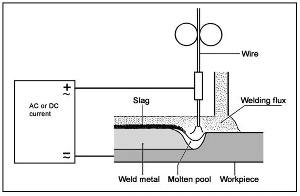
The flux also has a thermal insulating effect, and thus reduces heat losses from the arc. As a result, more of the input energy is available for the actual welding process itself than is the case with processes involving an exposed arc. The thermal efficiency is greater and the rate of welding is faster. It has been found that submerged arc welding has a thermal efficiency of about 90 %, as against an approximate value of about 75 % for MMA welding. Submerged arc welding can be performed using either DC or AC.
Application: -
Submerged arc welding can be employed for an extremely wide range of workpieces. The method is suitable for butt welding and fillet welding of such applications as structural members in ships, manufacture of pressure vessels, bridge beams, massive water pipes, thin sheet shells and so on. In addition, the process is particularly effective for cladding applications, e.g. when coating mild carbon steel with stainless steel materials, or when depositing hard materials on softer substrates.
Q.5)
3-2-1 PRINCIPLE
To perform properly, work-holders must accurately and consistently position the workpiece relative to the cutting tool, part after part. To accomplish this, the locators must ensure that the workpiece is properly referenced and the process is repeatable.
The Mechanics of Locating –
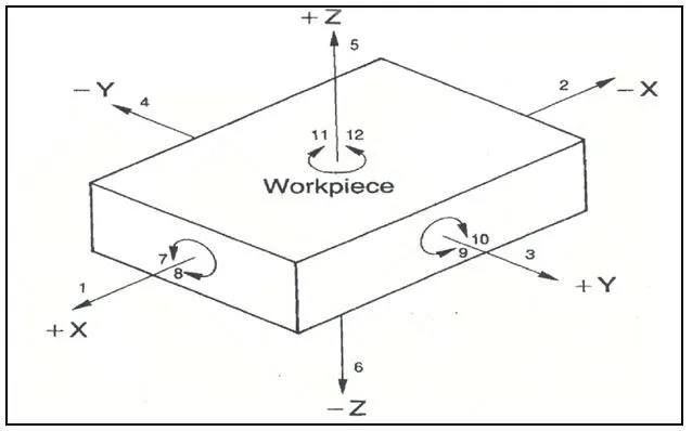
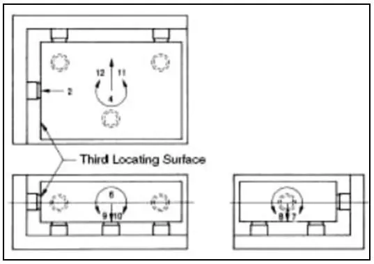
A workpiece free in space can move in an infinite number of directions. For analysis, this motion can be broken down into twelve directional movements, or "degrees of freedom." All twelve degrees of freedom must be restricted to ensure proper referencing of a workpiece.
As shown in below figure, the twelve degrees of freedom all relate to the central axes of the workpiece. Notice the six axial degrees of freedom and six radial degrees of freedom.
The axial degrees of freedom permit straight-line movement in both directions along the three principal axes, shown as x, y, and z. The radial degrees of freedom permit rotational movement, in both clockwise and counter/anti-clockwise radial directions, around the same three axes.
Locating a workpiece from its external edges is the most-common locating method. The bottom, or primary, locating surface is positioned on three supports, based on the geometry principle that three points are needed to fully define a plane. Two adjacent edges, usually perpendicular to each other, are then used to complete the location.
The most-common way to locate a workpiece from its external profile is the 3-2-1, or six-point, locational method. With this method, six individual locators reference and restrict the workpiece.
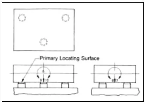
As shown in Figure 3-4, three locators, or supports, are placed under the workpiece. The three locators are usually positioned on the primary locating surface. This restricts axial movement downward, along the -z axis (#6) and radially about the x (#7 and #8) and y (#9 and #10) axes. Together, the three locators restrict five degrees of freedom.
The next two locators are normally placed on the secondary locating surface, as shown in Figure 3-5. They restrict an additional three degrees of freedom by arresting the axial movement along the +y axis (#3) and the radial movement about the z (#11 and #12) axis. The next two locators are normally placed on the secondary locating surface, as shown in Figure 3-5. They restrict an additional three degrees of freedom by arresting the axial movement along the +y axis (#3) and the radial movement about the z (#11 and #12) axis.
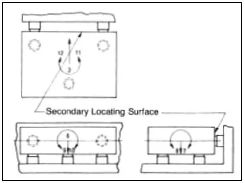
The final locator, shown in Figure 3-6, is positioned at the end of the part. It restricts the axial movement in one direction along the -x axis. Together, these six locators restrict a total of nine degrees of freedom. The remaining three degrees of freedom (#1, #4, and #5) will be restricted by the clamps.
Although cylindrical rest buttons are the most-common way of locating a workpiece from its external profile, there are also other devices used for this purpose. These devices include flat-sided locators, vee locators, nest locators and adjustable locators.
Q.6)
BODY CO-ORDINATE SYSTEM
In the assembly of body line, the role of the measurement systems of the fixtures are critical because from an poor design and misinterpretation of data can produce lose of time and lots of money. The most common technology used for measurements are the coordinate measuring machines, which can be mechanical CMM with stylus or optical CMM (laser trackers, interferometers) used for process validation.
The first prior step of using the measurement system is to verify its repeatability and reproducibility, in some cases, to estimate accuracy. The measurement system plays a critical role in any dimensional evaluation process. In the case of the automotive body, its role is particularly influential.
Body manufacturers measure most part features in absolute space (X, Y, and Z coordinates) rather than as relative distances between points [1]. Absolute space measurements are more complex, particularly for angled surfaces (i.e., not on measurement axis). They also are heavily dependent on the part locating system (i.e., datum scheme), which often is difficult for parts lacking rigidity.
One of the main components in a measurement system is the part reference or locating system. Regardless of the measurement technology, nearly all part measurements are relative to a part datum scheme described on Geometric Dimensioning and Tolerancing drawings. These datum schemes provide a reference system for all part surfaces and features using body coordinates. Figure 4 below illustrates a typical body coordinate system. This system replaces the traditional X, Y, and Z directional designations with fore/aft (X), in/out (Y), and up/down or high/low (Z). The 0,0,0 point of the car is the front, lower, and center position [1].
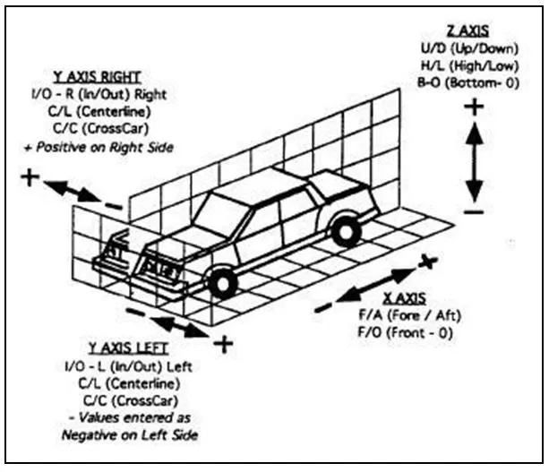
Reference axis system of the software is used for the design of the various features of the
parts (e.g. hole, fillet, threads,) To correlate the position of all the automotive components
during the final assembly the axis system of the vehicle is used. Most of the time vehicle
axis system and software axis system is the same. e.g. In most of European OEM, The X-axis represents the length of the vehicle Y-axis represents the width of the vehicle Z-axis
presents the height of the vehicle.
Y-axis is considered to be located at the front axle. All
BIW welding fixtures are designed with reference to the car line
These datum schemes provide a reference system for all part surfaces and features using
body coordinates. Figure below illustrates a typical body coordinate system. This system
replaces the traditional X, Y, and Z directional designations with fore/aft (X), in/out (Y), and
up/down or high/low (Z). The 0,0,0 point of the car is the front, lower, and centre position.
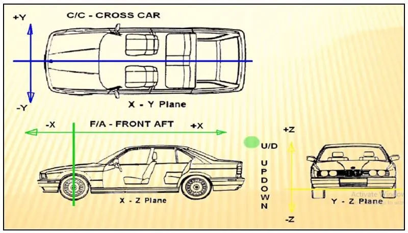
VEHICLE ORIENTATION: All vehicle product drawings are identified numerically relative to three vehicle planes described and shown below.
- X=Longitudinal direction (fore & after-F/A) or (Front O line-FOL).
- Y=Transverse direction (Cross car-C/C) or (Centre O line-COL).
- Z= Vertical direction (Up & down- U/D) or (Bottom O Line-BOL).
The origin of the body coordinate system (OX) is defined at the front centre of a vehicle. It indicates a length of car & the coordinate system (OZ) is below its underbody indicates height of car & the coordinate system (OY) its starting point is the centre of car body indicates width of car.
Q.7)
BODY PLANE SYSTEM
Body planes are the reference plane in an automotive car. These planes are used to define the GD & T of all car parts in a automotive domain. Body planes are three mutually perpendicular imaginary planes. These are generally considered to be present at the driver cabin or sometimes at the engine location or at the front end of the car depending on the customer.
The measurements from the body planes to the parts are called as body line dimension.
These body planes are called as
- FOL Front “O” line.
- COL Centre “O” line.
- BOL Body “O’ line.
The measurement along FOL or X-axis is called as F/A Front aft.
The measurement along COL or Y-axis is called as C/C Cross car.
The measurement along BOL or Z-axis is called as U/D Up down.
Bodyline dimensions are essential for the reasons stated below,
- It defines the exact position of each product in the vehicle w. r. t. a fixed origin.
- It ensures flawless design for assembly.
- While designing lines, all the designs are carried out relative to the bodyline, viz, fixture, turn table etc.
- It assists in easy location of different parts in a vehicle
- It aims in creating a standardized system.
- It assists in quality checks.
The above are the basic essential reasons that body line dimension would help in BIW.
It could help in designing lines like welding lines, assembly lines or car body through fixture & turntable etc. This help in designing every tools. Particular assembly or parts are designed w.r.t body line or an axis system or car line also helps in quality while doing CMM of that system.
CMM is basically done with the help of coordinates. It has related particular fixture with that car part, because that dimension, coordinates of hole & pin should match so it will help in quality check.