Week 2:- BiW Fixture Basics Challenge
- Begin work.
- Manage workflow for all project tasks.
- Issue management.
- Risk management.
- Manage change orders.
- Manage project communications with all stakeholders.
- Verify when milestones are reached.
- Conduct gateway reviews as required.

JOINING PROCESSES
• Joining includes welding, brazing, soldering, adhesive bonding of
materials.
• They produce permanent joint between the parts to be assembled.
• They cannot be separated easily by application of forces.
• They are mainly used to assemble many parts to make a system.
• Welding is a metal joining process in which two or more parts are joined
or coalesced at their contacting surfaces by suitable application of heat
or/and pressure.
• Some times, welding is done just by applying heat alone, with no pressure
applied
• In some cases, both heat and pressure are applied; and in other cases only
pressure is applied, without any external heat.
• In some welding processes a filler material is added to facilitate
coalescence(Joining)
Joining Processes: Welding, Brazing,
Soldering
1. Brazing and Soldering: Melting of filler rod only
• Brazing: higher temperature, ~brass filler, strong
• Soldering: lower temp, ~tin-lead filler, weak
2. Welding: Melting of filler rod and base metals
Advantages of welding:
• Welding provides a permanent joint.
• Welded joint can be stronger than the parent materials if a proper filler metal is
used that has strength properties better than that of parent base material and if
defect less welding is done.
• It is the economical way to join components in terms of material
usage and fabrication costs. Other methods of assembly require, for example,
drilling of holes and usage of rivets or bolts which will produce a heavier
structure.
Disadvantages of welding:
• Labour costs are more since manual welding is done mostly.
• Dangerous to use because of presence of high heat and pressure.
• Disassembly is not possible as welding produces strong joints.
• Some of the welding defects cannot be identified which will reduce the
strength.
How Does Resistance Welding Work?
Resistance welding is generally used to join two plain metal work pieces together. An electric current is delivered to the metal sheets (or any work pieces being joined) through weld electrodes which apply force to the sheets. This force is then converted to heat. The heat is generated so that it melts the metal at the point where they join – the point of ‘resistance’ between the faying surfaces. The electrode then extracts heat from the molten weld area which forms a weld nugget at the point where it solidifies. A force is applied before, during and after a current is applied, which confines the contact area.
Types of Resistance Welding
There are many resistance welding processes with different uses, such as spot welding, seam welding, and butt welding. Each one has a different specific welding application that makes it optimal for a particular situation.
1. Resistance Spot Welding
Resistance spot welding has been used extensively in the automotive industry for the joining of steel and in the aerospace industry for airframe components made from aluminium alloys. It is one of the oldest and simplest forms of resistance welding, in which a weld nugget is produced by passing an electric current between the two metal components whilst they are held together between electrodes, typically made from copper-based alloys due to its superior conductive properties.
2. Resistance Seam Welding
Resistance seam welding is a variation of the standard spot welding form, however instead of spot one nugget, a series of overlapping nuggets is produced. This is usually done by replacing the conventional spot welding electrodes with wheels, which turn as the parts are fed between them. The process thus produces a continuous welded seam rather than a single spot. Seam welding is often used in the production of thin sheet, leak-tight containers such as fuel tanks, and is generally unsuitable for welding aluminium.
3. Resistance Projection Welding
Resistance projection welding is a form of resistance welding where the electricity, force, and weld time are concentrated on raised ‘projections’ across the surface. Projection welding is generally used for welds using thicker materials than the thinner metal pieces that spot welding is usually required for, and often not metals. It is used primarily in the electrical, automotive and construction industries.
4. Resistance Butt Welding
Resistance butt welding is a process in which the two components of similar cross section can be joined together in one operation that takes place simultaneously across the entirety of the affected object, rather than just in small spots. The welding application of butt welding is often in wires and rods with small diameter measurements, generally up to about 16mm diameter.
5. Flash Butt Welding
Flash butt welding is similar, but in this case the energy transfer is primarily provided by the resistance heat arising from the parts themselves. This is a faster type of resistance welding where the welder joins the parts by applying some pressure, then by passing a heavy current through the joint which burns away surface irregularities. After the weld has generated enough heat, the parts are connected by applying heat and pressure simultaneously. This produces a forge butt weld with no melted metal remaining in the joint.
Advantages
- Similar and dissimilar metals are capable of being welded
- Highly automated
- Efficient with high production rate and high welding rate
- Cost-effective
- Environment-friendly, produces little waste or pollution
- No need for filler metal or extraneous materials such as rods, fluxes, inert gasses, oxygen, or acetylene are required
Disadvantages
- Complex and often high-cost machinery – a resistance welding machine generally requires a high level of technically trained personnel to use
- The thickness of the work piece is often limited
- It is less efficient for high conductive materials
- High electric power required
Fusion welding is a generic term for welding processes that rely on melting to join materials of similar compositions and melting points.[1] Due to the high-temperature phase transitions inherent to these processes, a heat-affected zone is created in the material[1]: 755 (although some techniques, like beam welding, often minimize this effect by introducing comparatively little heat into the workpiece[2]).
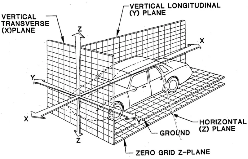
3-2-1 Principle of Location
The 3-2-1 principle of location (six point location principle) is used to constrain the movement of workpiece along the three axes XX, YY, and ZZ. This is achieved by providing six locating points, 3 pins in base plate, 2 pins in vertical plane and 1 pin in a plane which is perpendicular to first two planes.
(a) Definition of body coordinates. XYZ is centered at shoulder and determined on a body frame system. At the reference position where all joint angles are all zero, axis X points forward, Y points laterally, and Z is a cross product of X and Y, set along the long axis of upper arm.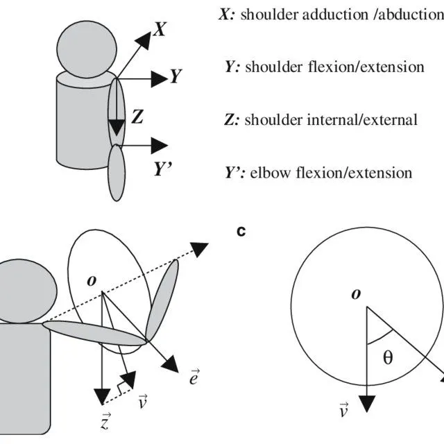
what Are Body Planes?
Body planes are hypothetical geometric planes used to divide the body into sections. They are commonly used in both human and zoological anatomy to describe the location or direction of bodily structures. Reference planes are the standard planes used in anatomical terminology and include:
- The sagittal plane (lateral or Y-Z plane) divides the body into sinister and dexter (left and right) sides. The midsagittal (median) plane is in the midline through the center of the body, and all other sagittal planes are parallel to it.
- The coronal plane (frontal or Y-X plane) divides the body into dorsal and ventral (back and front) portions. It also separates the anterior and posterior portions.
- The transverse plane (axial or X-Z plane) divides the body into superior and inferior (head and tail) portions. It is typically a horizontal plane through the center of the body and is parallel to the ground.
While these are the major reference planes of the body, other planes are commonly used in relation to these three. A longitudinal plane is any plane perpendicular to the transverse plane, while parasaggital planes are parallel to the saggital plane.
The coronal plane, the sagittal plane, and the parasaggital planes are examples of longitudinal
planes.