Week 2:- BiW Fixture Basics Challenge
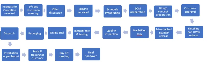
- What is the process of project execution activity?
 2. What are the types of joining processes?
A larger and more complex component or assembly is created by joining, which includes many processes. But there are two fundamentals for joining materials and components
- Mechanical joining
- Metallurgical joining
Mechanical joining
The technique of mechanical joining involves clamping or securing the two pieces together with screws, bolts, or rivets. Types of mechanical joining process
- Riveting
- Caulking
- Bolting
- Shrink fitting
- Folding
Advantages of mechanical joining
- Mechanical joining includes varieties and ease of use,
- Option to dismantle the product in cases where regular maintenance requires it.
- The ability to join dissimilar materials is another benefit.
Metallurgical joining
Fusion welding, pressure welding, and brazing/soldering are metallurgical joining techniques that make use of various energies.
Adhesives are also used in several chemical joining techniques.
Below are a type of metallurgical joining process
|
Fusion welding |
Electrical energy · Arc welding · Electron beam welding Chemical energy · Gas welding Light energy · Laser welding |
|
Pressure welding |
Electrical energy Resistance welding: · Resistance spot welding · Projection welding · Seam welding · Upset welding · Flash welding Chemical energy · Explosion welding Mechanical energy · Cold pressure welding · Friction welding · Friction stir welding (FSW) · Ultrasonic welding · Diffusion welding |
|
Brazing/soldering |
Electrical energy · Induction heating brazing (soft brazing = soldering) Chemical energy · Torch brazing (flame brazing) Light energy · Light beam brazing · Laser brazing |
3. What is Resistance Welding & its application in the automotive sector?
Resistance welding
It is a welding technology widely used in the manufacturing industry for joining metal sheets and components
The weld is made by conducting a strong current through the metal combination to heat up and finally melt at localized points predetermined by the design of the electrodes and/or the workpieces to be welded.
A force is always applied before during and after the application of current to confine the contact area at the weld interfaces and in some applications to forge the workpieces
Types of resistance welding
- Resistance spot welding
- Resistance seam welding
- Resistance projection welding
Resistance spot welding
The process is used for joining sheet materials and uses shaped copper-chromium or zirconium alloy electrodes to apply pressure and convey the electrical current through the workpieces
Heat is developed mainly at the interface between the two sheets, eventually causing the material being welded to melt, forming a molten pool, the weld nugget
The molten pool is contained by the pressure applied by the electrode tip and the surrounding solid metal
Advantage
- Short weld time and hence high weld speed
- Highly adaptable to automation and robotic techniques
- Typical BIW contains 5000 welds
- Strength and durability of automobile largely depends on quality of resistance spot welding
Resistance Projection welding
Projection welding is a resistance welding process for joining metal components or sheets with embossments by directly opposing forces with electrodes specially designed to fit the shapes of the workpiece
The current and the heat generation are localized by the shape of the workpieces either with their natural shape or specifically designed projection. Large deformation or collapse will occur in the projection part of the workpieces implying high pressure
Application
- Used for mechanical fixing of autobody structures
Eg weldnuts
Resistance seam welding
Seam welding is a resistance welding process for joining metal sheets in continuous, often leak tight seam joints by directly applying opposing forces with electrodes consisting of rotary wheels
The current and the heat generation are localized by the peripheral shapes of the electrode wheels
Application
- Seam welding is mostly applied in the manufacturing of containers, radiators and heat exchangers etc.
4. What is fusion welding & types of fusion welding with its application in the automotive sector?
Fusion welding:
Fusion welding is a process that uses heat to join or fuse two or more materials by heating them to a melting point. The process may or may not require the use of filler material. There are 5 major types of the fusion welding process
- Arc welding
- Laser welding
- Induction welding
- Oxyfuel welding
- Solid reactant welding
Arc Welding
The most popular type of fusion welding is arc welding. It is relying on an electric arc to join two or more objects. With electric arcs measuring up to 6,000 degrees Fahrenheit, this fusion welding process is highly capable of melting even toughest metals. Furthermore, arc welding can be performed underwater, making it an ideal solution for offshore welding projects. There are five types of arc welding
- Manual metal arc welding
- Gas- shielded metal arc welding
- Gas – shielded tungsten arc welding
- Submerged arc welding
- Plasma arc welding
Laser Welding
Another type of fusion welding is laser welding. It involves the use of light radiation to produce heat. The laser welding rig essentially blasts the surfaces with radiated light. With each blast, the surfaces become a little hotter. As the objects melt, they fuse together.
Induction Welding
Induction welding is distinguished from all other types of fusion welding because it’s the only one in which there’s no direct contact between an object’s surface and the heat source. With induction welding, a wrapped coil is used to create a magnetic field that heats metal. The magnetic field quickly heats the metal, causing to melt and fuse together.
Oxyfuel Welding
A type of chemical-based fusion welding, oxyfuel welding involves the use of a flame to heat and join surfaces, with oxygen as the fuel source. Fire, of course, needs oxygen, which is the basis on which oxyfuel welding works. The oxygen fuels the fire to create a hot flame in excess of 4,500 degrees Fahrenheit. Oxyfuel welding typically uses a combination of oxygen and flammable gas to create a hot flame to join objects.
Solid Reactant Welding
Finally, solid reactant welding is a type of fusion welding that relies on chemical reactions with certain materials to join them. There are compounds, for instance, that creates heat when mixed. Solid reactant welding uses this principle to join two or more objects.
5. What is the 3-2-1 principle?
For a fixture designer, the major portion of design time is spent deciding how to locate the work piece in the fixture.
You know that any free body has a total of twelve degrees of freedom as below:
6 translational degrees of freedom: +X, -X, +Y, -Y, +Z, -Z
And 6 rotational degrees of freedom:
- Clockwise around X-axis (CROT-X)
- Anticlockwise around X-axis (ACROT-X)
- Clockwise around Y axis (CROT-Y)
- Anticlockwise around Y axis (ACROT-Y)
- Clockwise around Z axis (CROT-Z)
- Anticlockwise around Z axis (ACROT-Z)
The best and most cost-effective method of part location is referred to as the 3-2-1 method.
(3) Minimum: Three locator blocks to establish the part plane. Three locators or supports are placed under the workpiece. The three locators are usually positioned on the primary locating surface. This restricts one axial movement downward and 4 radial movements. Together, the three locators restrict five DOFs
(2) Round locating pin in a round hole that defines a location in four directions(4- way) perpendicular to the plane previously established. This restricts four axial movement
(1) Round locating pin in a slot that defines two of the directions of the other pin. This restricts two axial movements
6. Define the Body coordinate system?
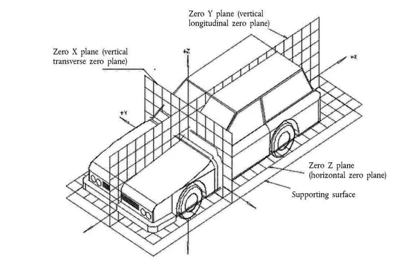
The body coordinate system has been widely used in the automotive industry for drawing of body parts, product and process design
A coordinate system is a reference system consisting of a set of points, line and surfaces used to define the positions of points in space in either two or three dimensions
In general BCS is also called as car line and the body line
X = Longitudinal direction [Fore & after F/A] or [ Front O line – FOL]
Y = Transverse direction [Cross car – C/C] or [ centre O line – COL]
Z = vertical direction [ Up & down – U/D] or [Bottom O line – BOL]
The origin of the body coordinate system (ox) is defined at the front centre of a vehicle, it indicates a length of car and the coordinate system (oz) is below its underbody indicates height of car, and the coordinate system (oy) its starting point is the centre of car body indicates width of car
7.Elaborate Body plane system & its essentials
Body planes are the reference planes in an automotive car. These planes are used to define the GD&T of all car parts in the automotive domain.
Body planes are 3 mutually perpendicular imaginary planes. These are generally considered to be present at the driver position or sometimes at the engine location or at the front end of the car, depending on the customer
The measurements from the body panes to the parts are called bodyline dimensions
The body planes are called as
- FOL Front ‘o’ Line
- COL Centre ‘o’ Line
- BOL Body ‘o’ Line
The measurement along FOL or X-axis is called F/A Front after
The measurement along COL or Y-axis is called as C/C cross car
The measurement along BOL or Z-axis is called as U/D Up Down
Bodyline dimensions are essential for the reasons stated below
- It defines the exact position of each product in the vehicle with respect to a fixed origin
- It ensures flawless design for assembly
- While designing lines, all the designs are carried out relative to the bodyline viz fixtures, turntable etc
- It assists in easy location of different parts in a vehicle
- It assists in quality check