Week 2:- BiW Fixture Basics Challenge
BiW Fixture Basics Challenge2
Question:1) What is the process of project execution activity?
Answer:-1)
Project Activity is basically a milestone, a section or a task that has many sub-tasks under it. In simple words, any activity that requires a number of tasks to be completed in order to complete that activity is known as a project activity.
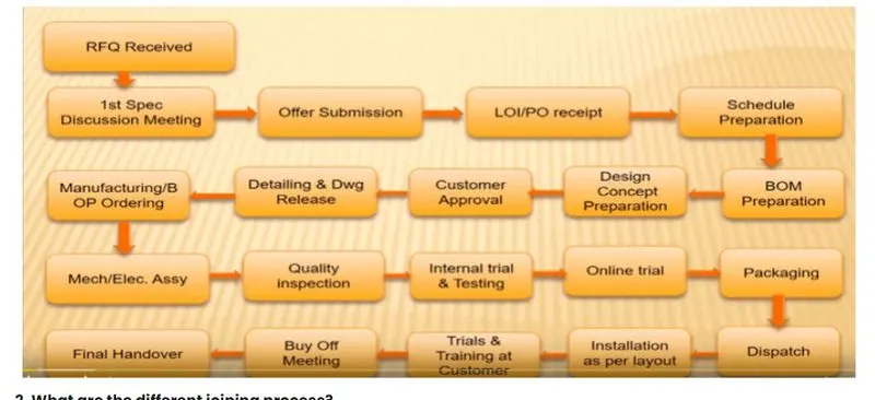
1)Request for Quote
An RFQ is a document used by companies to obtain information from vendors and suppliers, either for goods or services.
RFQ documents contain detailed specifications about what a company needs, such as technical requirements, length of the contract, required labor, or quantities of goods. Once RFQs have been created by the procuring company, they are sent to potential vendors that the company has an interest in working with, who can then respond with pricing quotes based on the requirements laid out.the tecinacal after commercial offer and the timeline for the completion of the project also specified by the customer
2)1st spec discussion meeting
After receiving the RFQ from the customer ,the documents regarding the technical after, commercial after and timeline are prepared .The timeline includes the time required for design simulation ,manufacturing till the installation of the product to the customer .
3)Offer Submission
Offer submission means documents and information entered into data entry fields that comprise an offeror’s response to a solicitation for bids, proposals, qualifications, or quotations conducted through an procurement platform or a paper-based submission process if allowed by the local unit in parallel with submission
To check whether the requirement are met in given time period
4) LOI/ PO Receipt
The customer studies the offer details and by the same time it also compares with the offer provided by the other suppliers/vendors and select the best suitable offer amongst them.
They released a purchase order .
5)Schedule Preparation
In project management, a schedule is a listing of a project's milestones, activities, and deliverables. Usually dependencies and resources are defined for each task, then start and finish dates are estimated from the resource allocation, budget, task duration, and scheduled events. A schedule is commonly used in the project planning and project portfolio management parts of project management. Elements on a schedule may be closely related to the work breakdown structure (WBS) terminal elements, the Statement of work, or a Contract Data Requirements List.
This will be the first perparation by the project where they schedule and a lot time to perform different production processes.
6) Bill of Materials Preparation
A bill of materials (BOM) is a centralized source of information used to manufacture a product. It is a list of the items needed to create a product as well as the instructions on how to assemble that product. Manufacturers that build products start the assembly process by creating a BOM.
7) Design Concept Planning
To Reduce the time and money CAD systems are introduced in our industry . we create a proper cad model in softwre and created their detail drawing .according to the cad model we can decide our production time and modification if needed
8) Customer Approval
It is in the interests of both Designer and Client to know that the requirements in the contract have been achieved, as well as ISO requirements if the Designer is certified to that standard. In this regard, checking and approval is a tool used by the Designer to mitigate its risk of inadequate work. It is also a technique expected by its Professional Indemnity (PI) insurers who want to limit their exposure.
Checking is scrutiny by the Designer of all the deliverables to be issued to assess their suitability to address the requirements set out in the contract. Deliverables can be made up of documents ,drawings, calculations, 3D design model outputs and other computer model outputs.
9)Detailing & DWG release-
After approval of drawing from customer design department release the drawing to the manufacturing unit
10) Manufacting BOP ordering -
The BO part like motors cylinder sensors gripper ecte required for manufacturing are ordered as per the design specification
11)Mechanical/ Electrical Assembly
The ordered part undergoes a prior quality control check and also they are checked for the required specification. Once the quailty check is done the mechanical and electrical part are assembled as per the design.
means documents and information entered into data entry fields that comprise an offeror’s response to a solicitation for bids, proposals, qualifications, or quotations conducted through an procurement platform or a paper-based submission process if allowed by the local unit in parallel with submission
To check whether the requirement are met in given time period
4) LOI/ PO Receipt
The customer studies the offer details and by the same time it also compares with the offer provided by the other suppliers/vendors and select the best suitable offer amongst them.
They released a purchase order .
5)Schedule Preparation
In project management, a schedule is a listing of a project's milestones, activities, and deliverables. Usually dependencies and resources are defined for each task, then start and finish dates are estimated from the resource allocation, budget, task duration, and scheduled events. A schedule is commonly used in the project planning and project portfolio management parts of project management. Elements on a schedule may be closely related to the work breakdown structure (WBS) terminal elements, the Statement of work, or a Contract Data Requirements List.
This will be the first perparation by the project where they schedule and a lot time to perform different production processes.
6) Bill of Materials Preparation
A bill of materials (BOM) is a centralized source of information used to manufacture a product. It is a list of the items needed to create a product as well as the instructions on how to assemble that product. Manufacturers that build products start the assembly process by creating a BOM.
7) Design Concept Planning
To Reduce the time and money CAD systems are introduced in our industry . we create a proper cad model in softwre and created their detail drawing .according to the cad model we can decide our production time and modification if needed
8) Customer Approval
It is in the interests of both Designer and Client to know that the requirements in the contract have been achieved, as well as ISO requirements if the Designer is certified to that standard. In this regard, checking and approval is a tool used by the Designer to mitigate its risk of inadequate work. It is also a technique expected by its Professional Indemnity (PI) insurers who want to limit their exposure.
Checking is scrutiny by the Designer of all the deliverables to be issued to assess their suitability to address the requirements set out in the contract. Deliverables can be made up of documents ,drawings, calculations, 3D design model outputs and other computer model outputs.
9)Detailing & DWG release-
After approval of drawing from customer design department release the drawing to the manufacturing unit
10) Manufacting BOP ordering -
The BO part like motors cylinder sensors gripper ecte required for manufacturing are ordered as per the design specification
11)Mechanical/ Electrical Assembly
The ordered part undergoes a prior quality control check and also they are checked for the required specification. Once the quailty check is done the mechanical and electrical part are assembled as per the design.
12) Quality Inspection
Checking quality of fixture that met the dimension tolerance zone and there should be no any manufacturing defect
13)Internal Trial and Testing
In this we do the internal testing of that fixture before delivering to the customer
14)Online Trails -
checking the performance with all the sensors , sequencing and controls . It checks whether everythings is being done as per the process.The successful completion of online trail is coveted to customers.
15) Packaging -
The finished product is packed properly when we are going to deliver it to the customer and there will be no scratch or dent happening .
16)Dispatch-
The finished product is delivered to the customer.
17) Installation as per Layout-
The fixture should be an assembly requirement of customer layout.
18)Trail and Training at the Customer-
We give training to customer how to handle that fixture
19)Buy -off meeting -
Buy off meeting takes place where the customer check whether the fixture meets the prescribed requirement as per the quotation and also checks the additional requirement at.
20) Final hand over -
Finally the fixture is given to the customer.
Question:2)What are the types of joining processes?
Answer:-2)
The durability and performance if any structure is largely dependent on the quality and design of the component joints.
Two fundamental options for joining material and component are : mechanical joining nad metallurgical joining
Metallurgical Joining -
Welding:
In olden days, in order to join two pieces of metals, riveting was done. But nowadays for joining two pieces of metal welding is done.
So, welding is a process of joining two pieces of metals by heating them.
Nowadays welding is used in almost all the industries since it is the easiest and rapid method of joining the metals.
Nowadays methods have also been developed to weld dissimilar metals. One important feature of welding is that the strength of the welded joint is more than 100% when compared to the metals.
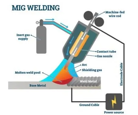
Welding Applications:
It is used in joining metals in following fields:
(a) In fabrication of tanks, vessels, boilers.
(b) In the automobile industry.
(c) In structural work, i.e., to fabricate trusses, frames.
(d) In pipe line fabrication.
(e) In ship building, motor building i.e., in general, in all the types of joining metals, welding is used.
Requirements of Good Welded Joints:
The following requirements of good welding joints are:
(i) For good welded joints, the surfaces should be clean. The cleaning can be done by using wire brush.
(ii) Proper edge preparation should be done as discussed below otherwise the joint may not have required strength. The edges must be prepared depending upon the thickness.
Various types of edge preparations for butt welds:
The square butt weld is used for the sheets having thickness between 1-5 mm.
Single V or Single U butt welds are used for the plates having thickness between 5-15 mm.
Double V or Double U butt welds are used for welding plates above 15 mm thickness.
Brazing:
Brazing is a process of joining two pieces of similar or dissimilar metals. In this case a non-ferrous metal or alloy in the molten form is supplied in between the metals to be joined and allowed to solidify.
The melting point of filler material is about 425°C but which is lower than the melting point of parent metals. During brazing no forging action is present and also the parent metal parts do not melt.
The various brazing metals and alloys are Copper, Brass, Bronze, Silver alloys, Aluminum alloys etc.
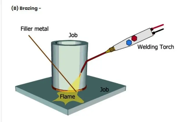
Types of Brazing Processes:
Based on heating source the various brazing processes are:
(i) Torch brazing
(ii) Furnace brazing
(iii) Resistance brazing etc.
Advantages:
(i) Dissimilar metals can be joined
(ii) It is a quick process
(iii) It is used for joining pipe fittings, carbide tips on the tools etc.
Limitations of Brazing:
- Brazing cannot be performed on hardened steel.
- Aluminum brazing needs a special technique and is very expensive
Soldering:
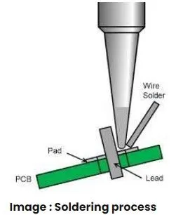
Soldering is a process of joining two pieces of metals. In this case a molten fusible metal called solder is supplied and allowed to solidify.
The melting point of solder is below 420° C. Generally Lead and Tin alloys are used as solder materials.
Some of the solders are:
(i) Soft Solder. Lead 37% and tin 63%.
(ii) Medium Solder. Lead 50% and tin 50%.
(iii) Electricians Solder. Lead 58 % and tin 42 %.
(iv) Plumbers Solder. Lead 70% tin 30%.
As one might have seen with the radio repairers that, when the current is supplied to the solder gun, the front end of it becomes hot. This hot end when brought in contact with solder material, it melts. This molten material is used for joining wires in radios, tape-recorders etc. The molten metal, when cools, produces solder joints.
Types of Soldering Processes:
(i) Soft Soldering:
It is used in sheet metal work and it has less strength.
(ii) Hard Soldering:
It is employed when stronger joint is required.
Based on the method of heating source, the soldering processes may be, resistance soldering, torch soldering, furnace soldering etc.
Application:
It is mainly used in joining wires in radios, tape-recorders, printed circuit boards etc.
Advantages:
- It produces liquid and gas-tight joints quickly.
- The cost of the joint is quite low.
- The temperature of soldering is low.
- The equipment used for soldering is simple, cheap and easy to handle.
- It is the most economical method.
Drawbacks:
The joints are not strong enough to withstand the constant jerks and pulls, which is the main drawback of the process
Mechanical joining -
Rivet
Riveting is a metal joining Process in which the two metallic parts are joined by the use of rivets. In this process, the metallic parts to be joined do not undergo any change in their physical structure or atomic structure. However Force is required for riveting Riveting is used widely in automobile and aerospace industry and in many other applications where we require permanent/semi-permanent bonding and where bolting and welding is not an option. Mostly done for low thickness sheet metals and Aluminium
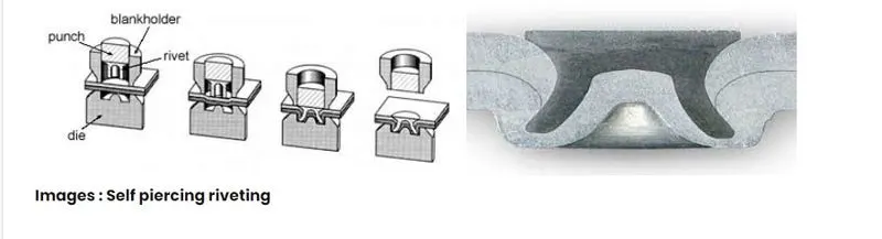
Hemming
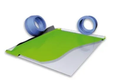
Hemming is a forming operation in which the edges of the sheet are folded or folded over another part in order to achieve a tight fit. Normally hemming operations are used to connect parts together, to improve the appearance of a part and to reinforce part edges.
In car part production, hemming is used in assembly as a secondary operation after deep drawing, trimming and flanging operations to join two sheet metal parts (outer and inner) together. Typical parts for this type of assembly are hoods, doors, trunk lids and fenders.
The accuracy of the hemming operation is very important since it affects the appearance of the surface and surface quality. Material deformations, which occur during the hemming process, can lead to dimensional variations and other defects in parts. Typical hemming defects are splits or wrinkles in the flange, material overlaps in the corner areas or material roll-in. This is why it is important to use simulation tools in order to, on the one hand, better understand the hemming process and, on the other hand, significantly reduce the number of “trial and error” loops during tryout und production.
There are various types of hemming operations:
- Conventional die hemming
- Roll hemming
Question:3)What is Resistance Welding & its application in the automotive sector?
Answer:-3)
Resistance welding is the joining of metals by applying pressure and passing current for a length of time through the metal area which is to be joined. The key advantage of resistance welding is that no other materials are needed to create the bond, which makes this process extremely cost effective.
There are several different forms of resistance welding (e.g. spot and seam, projection, flash, and upset welding) which differ primarily by the types and shapes of weld electrodes that are used to apply the pressure and conduct the current. The electrodes, typically manufactured from copper based alloys due to superior conductive properties, are cooled by water flowing through cavities inside the electrode and the other conductive tooling of the resistance welding machine.
Resistance welding machines are designed and built for a wide range of automotive, aerospace and industrial applications. Through automation, the action of these machines is highly controlled and repeatable allowing manufacturers to staff production readily.
Types of Resistance Welding Applications:
-
Spot Welding and Seam Welding
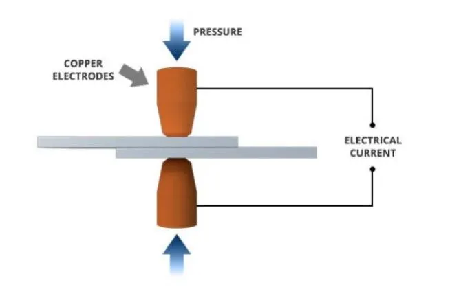
- Resistance Spot Welding, like all Resistance Welding Processes, creates welds using heat generated by resistance to the flow of welding current between the faying surfaces, as well as force to push the workpieces together, applied over a defined period of time. Resistance Spot Welding uses the face geometries of the welding electrodes themselves to focus the welding current at the desired weld location, as well as to apply force to the workpieces. Once sufficient resistance is generated, the materials set down and combine, and a weld nugget is formed.
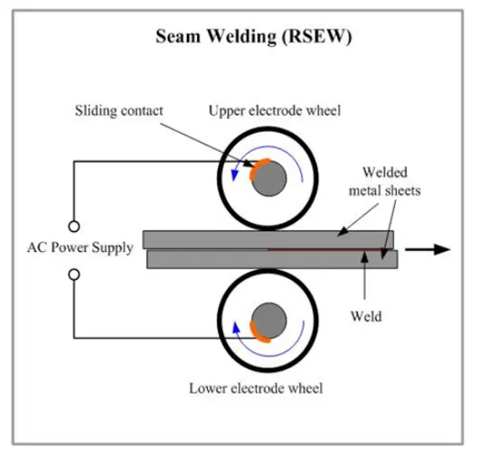
- Resistance Seam Welding is a subset of Resistance Spot Welding using wheel-shaped electrodes to deliver force and welding current to the parts. The difference is that the workpiece rolls between the wheel-shaped electrodes while weld current is applied. Depending on the particular weld current and weld time settings, the welds created may be overlapping, forming a complete welded seam, or may simply be individual spot welds at defined intervals.
-
Projection Welding
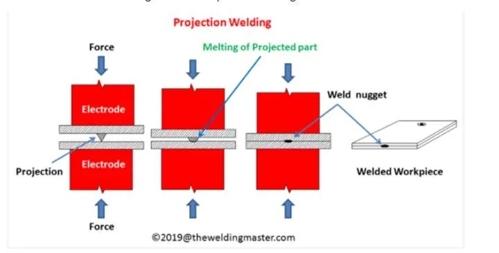
- Like other Resistance Welding Processes, Projection Welding uses heat generated by resistance to the flow of welding current, as well as force to push the workpieces together, applied over a defined period of time. Projection Welding localizes the welds at predetermined points by using projections, embossments or intersections, all of which focus heat generation at the point of contact. Once the weld current generates sufficient resistance at the point of contact, the projections collapse, forming the weld nugget.
- Solid Projections are often used when welding fasteners to parts. Embossments are often used when joining sheet or plate material. An example of Projection Welding using material Intersections is cross-wire welding. In this case the intersection of the wires themselves localizes heat generation, and therefore resistance. The wires set-down into one another, forming a weld nugget in the process.
Question:4)What is fusion welding & types of fusion welding with its application in the automotive sector?
Answer:-4)
Fusion welding is a process that uses heat to join or fuse two or more materials by heating them to melting point. The process may or may not require the use a filler material. External application of pressure is not required for fusion welding processes, except for resistance welding, where substantial contact pressure is required during welding for sound joining.
- Arc Welding Process
Arc welding is among the preferable ways of a fusion welding process. True to the hype, arc welding connects two parts (or more) using an electric arc. The reason is that electric arcs generate heat levels that reach up to 6,000 degrees Fahrenheit, making them ideal for fusing hard metals and materials. Additionally, arc welding is also suitable for offshore applications where you can perform underwater fusion welding. Commonly, arc welding processes include:
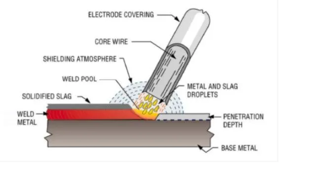
Shielded Metal Arc Welding (SMAW): Commonly used for welding non-ferrous and ferrous materials in nearly all positions. also known as manual metal arc welding (MMA or MMAW), flux shielded arc welding or stick welding. Suitable for welding ferrous and non-ferrous materials in all positions.
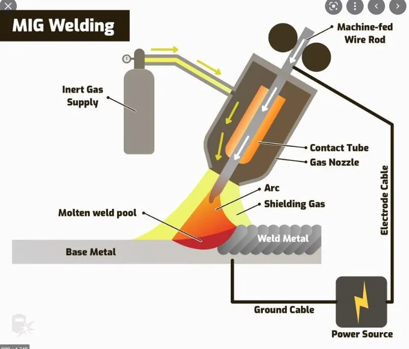
Metal Inert Gas Welding (MIG) and Metal Active Gas Welding (MAG), also known as Gas Metal Arc Welding (GMAW). MIG and MAG welding are the most common arc welding processes, in which an electric arc forms between a consumable wire electrode and the workpiece leading them to melt and join. Both use a shielding gas to protect the weld from airborne contaminants, or oxidation in the case of MIG welding.
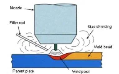
Tungsten Inert Gas Welding (TIG), also known as Gas Tungsten Arc Welding (GTAW). This arc process uses a non-consumable tungsten electrode to create the arc between the electrode and the base plate. An inert shielding gas is used to protect from oxidation or other atmospheric contamination. This process can be used autogenously on thin parts, but will require the addition of a wire, rod, or consumable to be added for thicker parts.
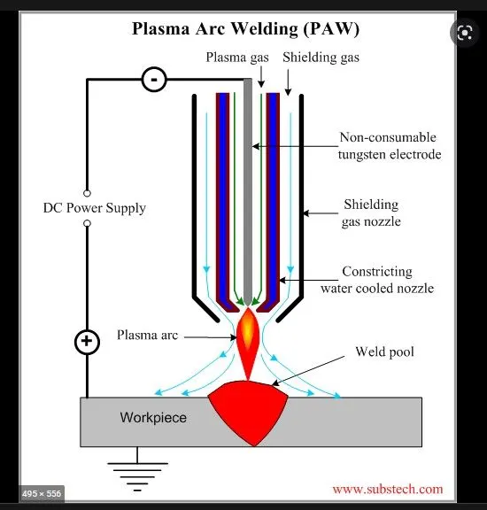
Plasma Arc Welding (PAW). This process uses an electric arc created between an electrode and the torch nozzle. The electric arc ionises the gas (usually argon) in the chamber creating what is called a 'plasma.' It is then forced through a fine bore copper nozzle that constricts the arc and directs it to the workpiece, allowing the plasma arc to be separated from the shielding gas (which is usually made from a mixture of argon and hydrogen)
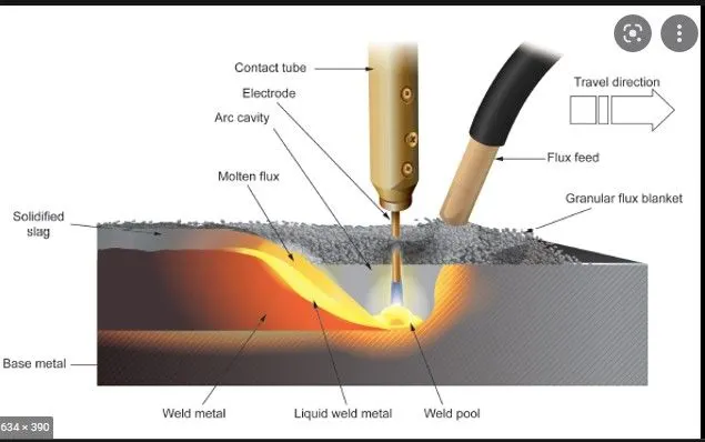
Submerged Arc Welding (SAW). This frequently-used arc welding process uses a continuously-fed consumable electrode and a blanket of fusible flux which becomes conductive when molten and provides a current path between the workpiece and the electrode. The flux also prevents spatter and sparks while suppressing ultraviolet radiation and fumes.
Question:5)What is the 3-2-1 principle?
Answer:-5)
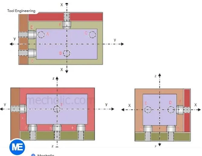
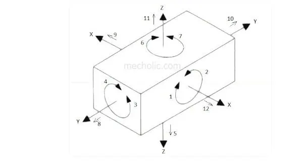
The 3-2-1 principle of location (six point location principle) is used to constrain the movement of workpiece along the three axes XX, YY, and ZZ. This is achieved by providing six locating points, 3 pins in base plate, 2 pins in vertical plane and 1 pin in a plane which is perpendicular to first two planes.
A workpiece will be completely confined when blanked against:
- 3 points in one plane: The “3” in 3-2-1 refers to 3 locators (passive fixture elements) on the primary locating/datum surface.
- 2 points in another plane: The “2” in 3-2-1 refers to 2 locators on the secondary locating/datum surface.
- 1 point in a third plane: The “1” in 3-2-1 refers to 1 locator on the tertiary locating/datum surface
Question:6)Define Body coordinate system?
Answer:-6)
BODY COORDINATE SYSTEM
It is coordinete system consisting of set of point ,lines, nad surfcae , used of define the postion of point space in either two or threre dimensions
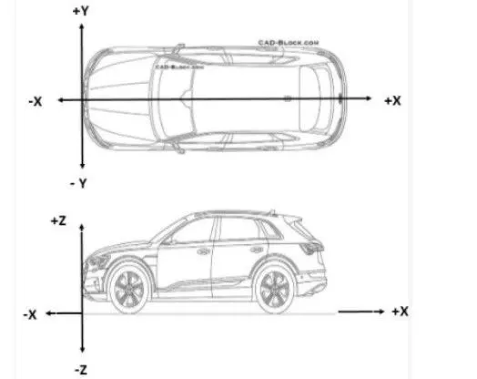
To repersent the position of BIW car parts weilding fixture and its unit assemblies with its individal parts (eg. the part which are in contact with panel) in 2D drawing their respective position are shown with reference to (x=0, y=0,z=0) position.In short it shown in 2D XY,YZ,XZ coordinate position
of BIW welding fixture part or assemblies with referance to orgin X=0,Y=0,Z=0
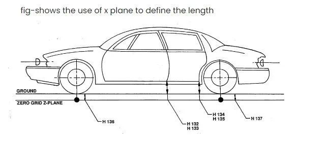
- The length of the car is the X- axis .This is called front O line .
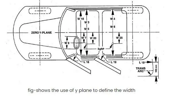
- The length of the car is the Y- axis .This is called center O line .
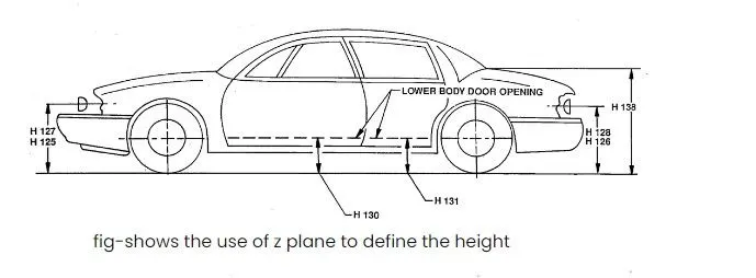
- The length of the car is the Z- axis .This is called bottom O line .
Question:7)Elaborate Body plane system & its essentials.
Answer:-7)
Body plane are three mutually perpendicular imadinary planes .These are reference planes in automotive car These are used to define GD & T of all part in automative domain.
The measurment from body plane to part are called body plane dimasions.
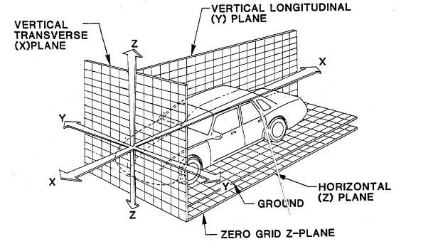
Bodylines dimension are essential for below reason
1.It define exact postion of each product in the viehicle w.r.t a fixed orgin
2.It ensure flawless design for assembly
3.While desgning lines , all the design are carried out relative to the bodylines viz Fixture , Turntables etc.
4. It assist in easy location of diffrent parts in yhe vehicle
5.It aims in creating a standardized system.
6.It assist in quality checks
Some example which shows how we use body plane to define the exact position of part is shown below.