Week 2 Bevel Gear Challenge
AIM :
To Simulating the Bevel Gear Setup and perform grid dependency test. All should be done by Using ANSYS Static Structural Analysis.
OBJECTIVES :
Perform baseline simulation by using 4mm Element Size.
Grid Dependency Test by Using 5mm & 6mm Element Size.
To Solve the Total Deformation, Equivalent Elastic Strain & Equivalent Von Mises Stress.
Comparing the all results and findout the best.
INTRODUCTION :
A Bevel Gears are used to power transmission component which is primarily used for transmit the rotatary motion from one shaft to another shaft with non parallel axis, but the angle between the axis is not exceed beyond the 90 degree. And also, it's used to increase the torque of the output power and decrease the speed of the output power.
Basically, Small gear are called as pinion and big gear is called as crown gear or bevel gear.
Common Applications are used by bevel gear is Automotive Differential Unit in the live axle and Hand drill machine which helps us to give the feed.
Grid Dependency Test :
Grid Dependency test is simply says, it is used to finding the proper element size for the simulation and used to reduce the discritization error. If we reduce the element size continuously over a period of time, a simulation results will not changed respective to element size.
If we further reducing the element size, by results it leads to computational cost & calculating time taken is increased.
PROCEDURE FOR ATTAINING THE OBJECTIVES :
I) CAD MODEL :
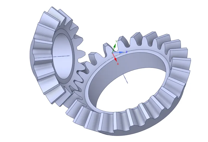
A Bevel Gear CAD Model is given from design team. We have to import the model into our Static structural analysis case setup. Inorder to view the model, open a space claim or Design modeler will shown up like as below image.
II) Assigning Material :
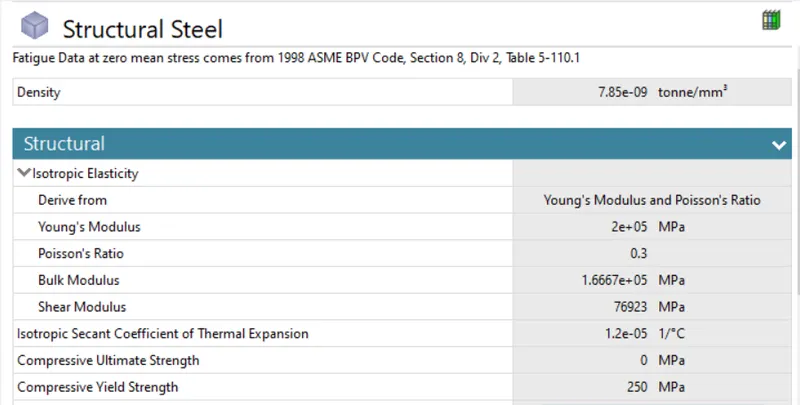
Once open the Mechanical model, we have to assigning the material to the component.
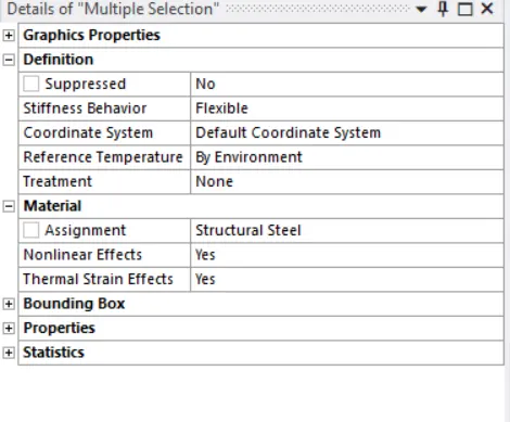
Assigning the structural steel as a material for ths case.
III) Connections :
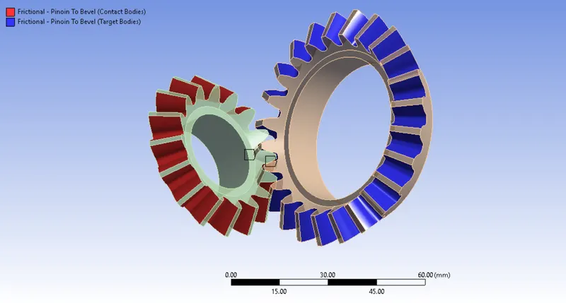
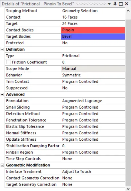
Select the tooth faces for the crown gear as a contact bodies & click the apply and followingly select the tooth faces for the pinion gear as a Target Bodies.
Keep "Frictional" as a contact type, which maintain frictional force between the contacted surface based on Friction coefficient. In this case, we can also use "Frictionless" type, because there's no friction coefficient between them.
Keep "Symmetric" as a Behavior of the contact, which assume contact & Target are same. Also, it leads to quick convergence.
Keep Formulation as "Augmented Lagrange" Algorithms which help to increase the stiffness of the contact and resists the penetration between them. This type of algorithms are used any type of contact.
Keep Interface Treatment as "Adjust to Touch", which make touch to eachother instead gaps between them and also avoid the penetration between them.
Apart from those things, keep default settings as it is.
Joints :
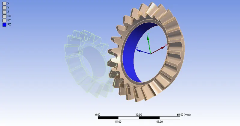
Create a new Joints under the connection tree outline. Select the inner face of the Crown gear, it will automatically constraints the degree of freedom at RZ which means allow the rotation of about Z direction in the Referance coordinate axis.
Make sure select the Body to Ground for Connection Type and type of motion is Revolute.
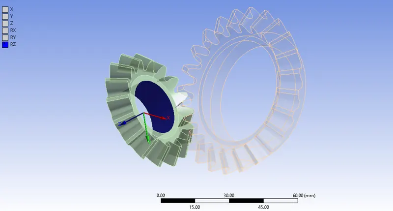
Similarly, we follow the same procedure to do for Pinion gear also.
V) Meshing :
Basically, To divide the entire model into infinitesimal control volume, that frame work is called Meshing. This process is called Discritization. This FEM is widely used for solving partial differential equation in different physical field such as Structural problem, Heat transfer problem, Fluid flow problem, Electro magnetic Analysis & Acoustics Analysis.
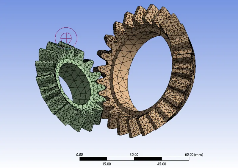
Element Size = 6 mm
Face Mesh Element Size = 2 mm
Element Type = Volumetric meshing with Tetrahedrons or Tetrahedrals element
No of Nodes = 30052
No of Elements = 17789
Reason for fine the mesh on the face surface alone is, since we only look into stress developed on the tooths and contact between them. Inorder to get to capture the accurate results on the tooth surface, we have to refine on it.
We keep "Program Controlled" for Element Order, so Ansys takes a second order elements, each Tetra elements have 10 nodes itself. By results, it take more time for solving as compared to First order elements & increasing storage space also. But, results has been more accurate as compared then first order discritization.
After done the meshing on the model, it has looks as shown in below image.
VI) Analysis Settings :
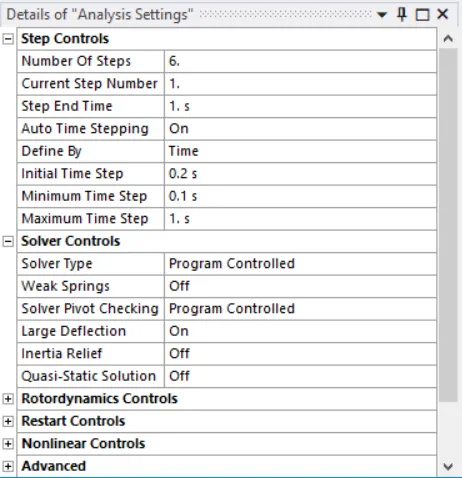
Increase the number of time step = 6
Auto Time Stepping = On
Define By = Time
Initial Time Step = 0.2 sec
Minimum Time Step = 0.1 sec
Maximum Time Step = 1 sec
Large Deflection = On
Boundary Condition :
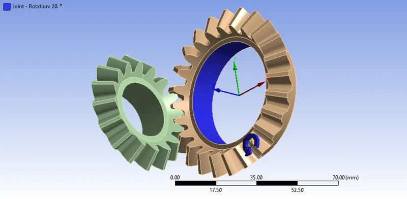
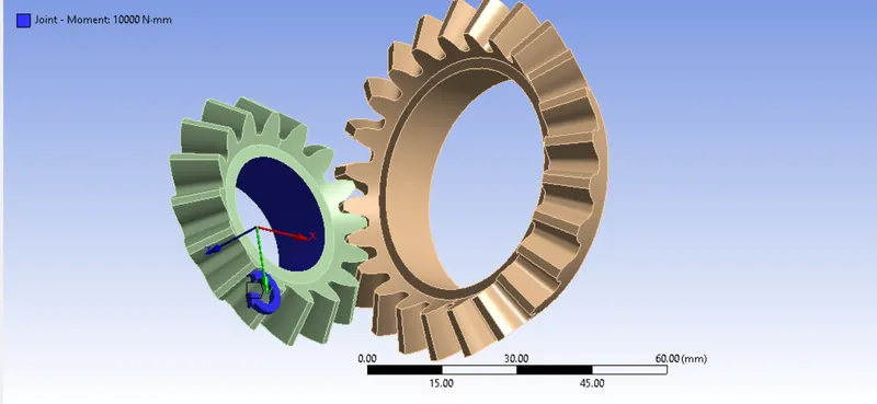
In General, Rotational power is transmit from Pinion to Crown. So, we provide a Moment Boundary condition to Pinion and Rotational Boundary condition to Crown.
Joint - Rotation :
Joint = Ground to Crown ( Big Gear)
Type of Joint = Rotational
Degree of Freedom = Rotation about Z axis
Magnitude = Tabular data
Tabular data = Rotation is 0 degree to 120 degree with 20 degree interval or 6 time steps.
Joint - Moment :
Joint = Ground to Pinion (Small Gear )
Type of Joint = Moment
Degree of Freedom = Rotation about Z axis
Magnitude = Tabular data
Tabular Data = 10 KN Constant Moment acting on each time step.
RESULTS :
Equivalent Stress :
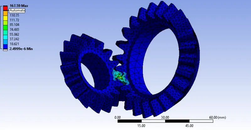
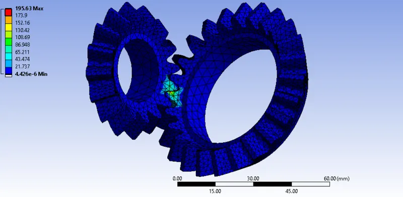
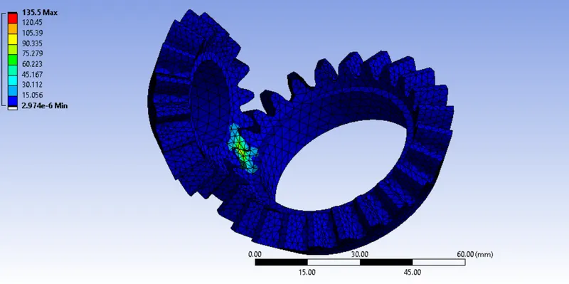
Equivalent Von Mises stress is also called as Maximum Distortion Stress Theory. A Structural Steel Material have Yield Stress value by determined using a tensile test. So, Simulation Equivalent Von Mises stress will not cross the limit of Yield stress value of the material, if happens, it might be failed. Inorder to prevent the material failed, make sure we have to apply a Permissible Load.
In this case, maximum stress generation is less than material yield stress. So, this load is safe.
Equivalent Stress for 6 mm :
Equivalent Stess for 5 mm :
Equivalent Stress for 4 mm :
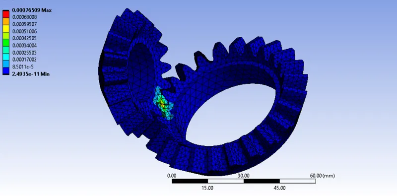
Equivalent Elastic Strain :
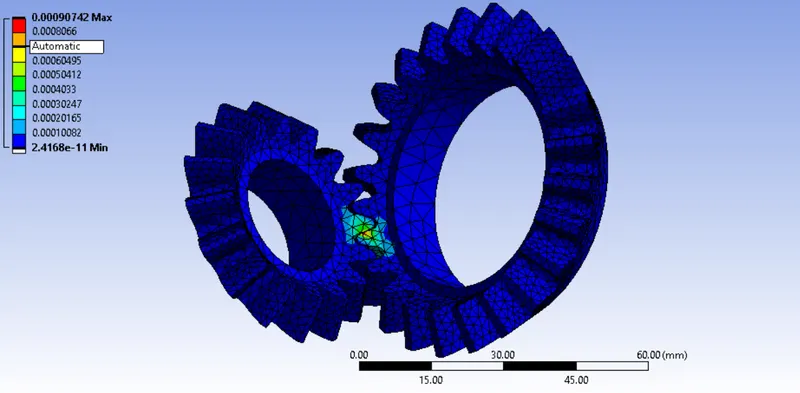
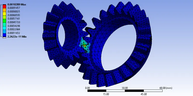
The Equivalent Elastic Strain is related to Equivalent Von Mises Stress, By using Stress & Young's modulus value based on applied load to which calculate the Equivalent Elastic Strain value as a output.
Equivalent Elastic Strain for 6 mm:
Equivalent Elastic Strain for 5 mm:
Equivalent Elastic Strain for 4 mm:
Total Deformation :
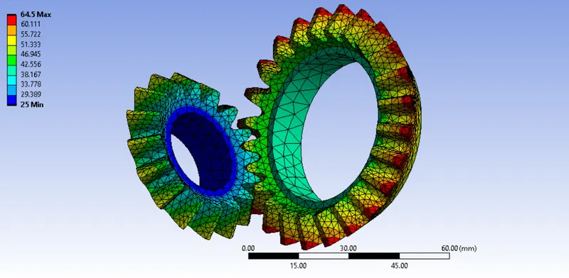
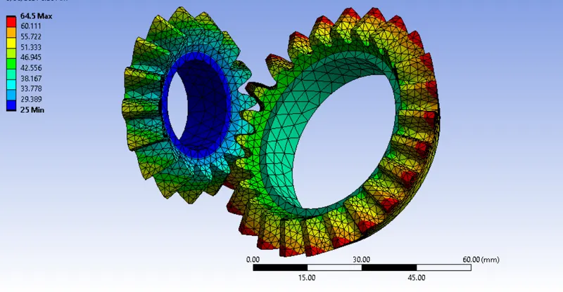
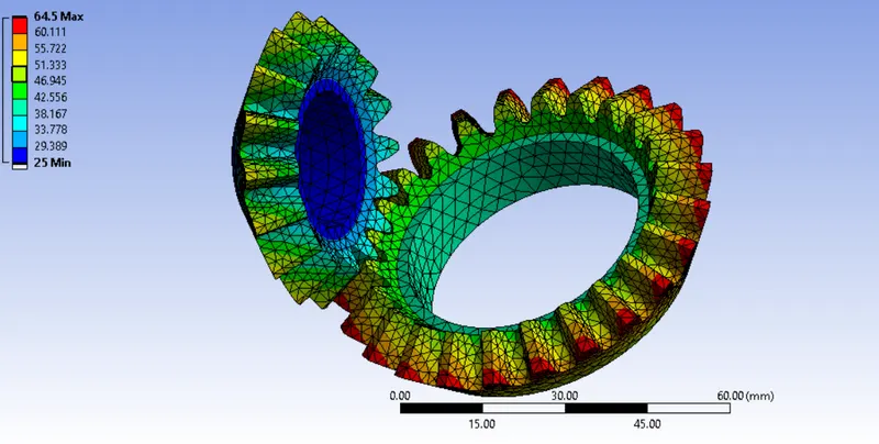
Total Deformations are pretty same for all cases. A Maximum deformation occurs on the crown wheel at tip of the tooth for all the cases.
Total Deformation for 6 mm :
Total Deformation for 5 mm :
Total Deformation for 4 mm :
CONCLUSION :
| Mesh Element Sizes | Equivalent Von Mises Stress (Mpa) | Equivalent Elastic Strain | Total Deformation in mm |
| 6 mm | 167.59 | 0.00090742 | 64.5 |
| 5 mm | 195.63 | 0.00102089 | 64.5 |
| 4 mm | 135.5 | 0.00076509 | 64.5 |
We Performed three different element size on a same component & same material as well. According to the grid dependency test, a solution results has slightly accuracy for 5mm as compared to 6 mm element size. But, In element size 4 mm has drastically varying as compared to element size 5 mm & 6 mm. So, element size 4 mm results are wouldn't be helpful.
Recommended element size is 5mm which gives acceptable results for us.