Week 2 Bevel Gear Challenge
Bevel Gear Challenge
Problem statements:
- To explain the grid dependency test and its uses.
- To perform a grid dependency test for the Bevel gear simulation for mesh sizes of 5, 4 and 2 mm and solve for Von-Mises stress, Equivalent elastic strain, and Total Deformation using the previously mentioned mesh sizes.
Tools used:
ANSYS Workbench 2020 R2
Boundary conditions (Same for all 3 analyses except mesh size):
Part type = Bevel Gears mated at a right angle
Material = Structural Steel
Rotation = 120 degrees
Moment load = 100 Nmm
Material properties
| Sl. No. | Properties | Units | Structural Steel |
| 1 | Density | kg/m3 | 7800 |
| 2 | Young's Modulus | MPa | 200000 |
| 3 | Tensile Yield Strength | MPa | 350 |
| 4 | Tensile Ultimate Strength | MPa | 420 |
| 5 | Shear Modulus | MPa | 79300 |
| 6 | Poissons Ratio | N/A | 0.25 |
Case 1: 6mm mesh size
- Setup: A new Static Structural study was created in ANSYS Workbench.
- Boundary conditions: Structural steel was applied as the material.
- Frictional contact is established between the small and the large gear.
- The gears are secured using revolute joints.
- Mesh: A mesh size of 6 mm is chosen for all bodies and then a finer mesh of 1.75 mm is chosen for certain surfaces where refinement is required using face sizing.
- Loads: A moment of 100 Nmm was applied and an angular displacement of 120mm in 6 steps was defined to replicate the rotation of the gears.
- Results: The mesh is generated and Stress, Strain, and Deformation are chosen as the solutions to be evaluated. The results are tabulated in the results section of the report.
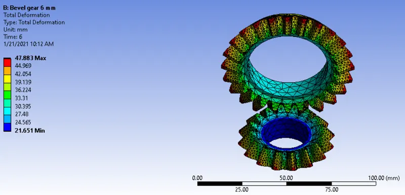
Figure 1: Total Deformation with 6 mm mesh size
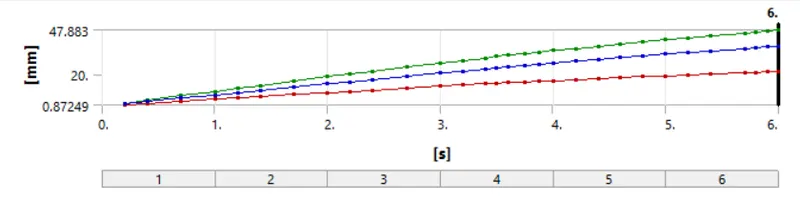
Figure 2: Total Deformation plot with 6 mm mesh size
| Time [s] |
Minimum [mm] | Maximum [mm] | Average [mm] | |
| 1 | 0.2 | 0.87249 | 1.8939 | 1.4263 |
| 2 | 0.4 | 1.7439 | 3.7856 | 2.8554 |
| 3 | 0.7 | 3.0467 | 6.6136 | 5.0044 |
| 4 | 1 | 4.3412 | 9.4236 | 7.1073 |
| 5 | 1.2 | 5.1978 | 11.283 | 8.506 |
| 6 | 1.4 | 6.048 | 13.129 | 9.91 |
| 7 | 1.7 | 7.3093 | 15.866 | 12.012 |
| 8 | 2 | 8.5505 | 18.561 | 14.065 |
| 9 | 2.2 | 9.3652 | 20.329 | 15.414 |
| 10 | 2.4 | 10.168 | 22.073 | 16.762 |
| 11 | 2.7 | 11.35 | 24.637 | 18.765 |
| 12 | 3 | 12.5 | 27.134 | 20.735 |
| 13 | 3.2 | 13.248 | 28.758 | 22.013 |
| 14 | 3.4 | 13.98 | 30.346 | 23.27 |
| 15 | 3.5 | 14.339 | 31.127 | 23.9 |
| 16 | 3.6 | 14.695 | 31.898 | 24.522 |
| 17 | 3.75 | 15.219 | 33.036 | 25.449 |
| 18 | 3.875 | 15.648 | 33.968 | 26.218 |
| 19 | 4 | 16.07 | 34.883 | 26.982 |
| 20 | 4.2 | 16.728 | 36.312 | 28.156 |
| 21 | 4.4 | 17.366 | 37.698 | 29.311 |
| 22 | 4.6 | 17.983 | 39.037 | 30.446 |
| 23 | 4.8 | 18.579 | 40.329 | 31.564 |
| 24 | 5 | 19.151 | 41.572 | 32.661 |
| 25 | 5.2 | 19.7 | 42.764 | 33.732 |
| 26 | 5.4 | 20.225 | 43.904 | 34.756 |
| 27 | 5.7 | 20.967 | 45.855 | 36.245 |
| 28 | 5.8 | 21.201 | 46.534 | 36.73 |
| 29 | 5.9 | 21.429 | 47.213 | 37.211 |
| 30 | 6 | 21.651 | 47.883 | 37.683 |
Table 1: Total Deformation table with 6 mm mesh size
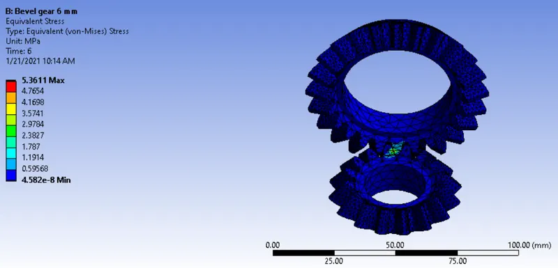
Figure 3: Equivalent Stress with 6 mm mesh size
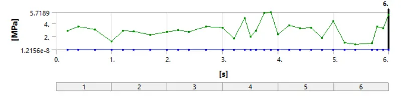
Figure 4: Equivalent Stress plot with 6 mm mesh size
| Time [s] | Minimum [MPa] | Maximum [MPa] | Average [MPa] | |
| 1 | 0.2 | 1.45E-08 | 2.8924 | 1.10E-02 |
| 2 | 0.4 | 2.86E-08 | 3.554 | 1.28E-02 |
| 3 | 0.7 | 2.15E-08 | 3.0972 | 1.15E-02 |
| 4 | 1 | 2.22E-08 | 1.3008 | 8.67E-03 |
| 5 | 1.2 | 2.33E-08 | 2.9125 | 1.16E-02 |
| 6 | 1.4 | 2.38E-08 | 2.7932 | 1.10E-02 |
| 7 | 1.7 | 2.84E-08 | 2.2971 | 1.01E-02 |
| 8 | 2 | 2.57E-08 | 2.6798 | 9.35E-03 |
| 9 | 2.2 | 2.56E-08 | 2.9847 | 1.20E-02 |
| 10 | 2.4 | 2.81E-08 | 2.7244 | 1.14E-02 |
| 11 | 2.7 | 9.51E-08 | 3.5652 | 1.36E-02 |
| 12 | 3 | 2.56E-08 | 3.3598 | 1.25E-02 |
| 13 | 3.2 | 2.42E-08 | 1.7172 | 8.72E-03 |
| 14 | 3.4 | 2.54E-08 | 4.7929 | 1.26E-02 |
| 15 | 3.5 | 2.55E-08 | 2.023 | 9.03E-03 |
| 16 | 3.6 | 2.63E-08 | 2.9033 | 1.17E-02 |
| 17 | 3.75 | 2.88E-08 | 5.6298 | 1.39E-02 |
| 18 | 3.875 | 1.54E-07 | 5.7189 | 1.41E-02 |
| 19 | 4 | 2.94E-08 | 2.3811 | 1.05E-02 |
| 20 | 4.2 | 1.22E-08 | 3.7059 | 1.22E-02 |
| 21 | 4.4 | 1.62E-08 | 3.2265 | 1.25E-02 |
| 22 | 4.6 | 1.59E-08 | 3.3228 | 1.26E-02 |
| 23 | 4.8 | 1.92E-08 | 1.8436 | 8.77E-03 |
| 24 | 5 | 1.44E-07 | 4.3206 | 1.43E-02 |
| 25 | 5.2 | 2.58E-08 | 1.1162 | 7.79E-03 |
| 26 | 5.4 | 2.67E-08 | 0.81402 | 7.48E-03 |
| 27 | 5.7 | 2.58E-08 | 1.0261 | 8.43E-03 |
| 28 | 5.8 | 2.78E-08 | 3.55 | 1.16E-02 |
| 29 | 5.9 | 1.06E-07 | 3.2869 | 1.20E-02 |
| 30 | 6 | 4.58E-08 | 5.3611 | 1.35E-02 |
Table 2: Equivalent Stress table with 6 mm mesh size
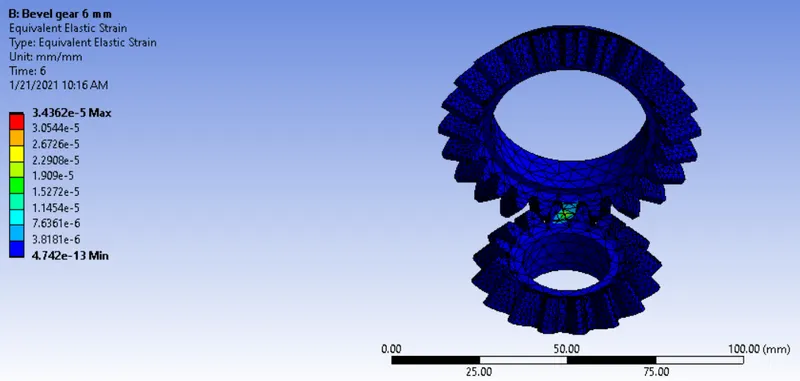
Figure 5: Equivalent Strain with 6 mm mesh size
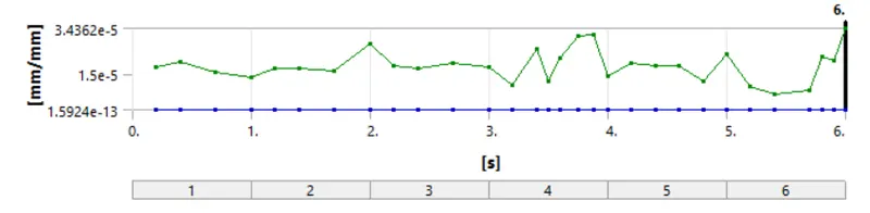
Figure 6: Equivalent Strain plot with 6 mm mesh size
| Time [s] | Minimum [mm/mm] | Maximum [mm/mm] | Average [mm/mm] | |
| 1 | 0.2 | 1.93E-13 | 1.81E-05 | 6.80E-08 |
| 2 | 0.4 | 2.32E-13 | 2.00E-05 | 7.78E-08 |
| 3 | 0.7 | 2.15E-13 | 1.61E-05 | 6.85E-08 |
| 4 | 1 | 2.24E-13 | 1.38E-05 | 5.43E-08 |
| 5 | 1.2 | 2.12E-13 | 1.75E-05 | 7.04E-08 |
| 6 | 1.4 | 2.12E-13 | 1.76E-05 | 6.79E-08 |
| 7 | 1.7 | 2.90E-13 | 1.62E-05 | 6.25E-08 |
| 8 | 2 | 1.64E-13 | 2.76E-05 | 6.09E-08 |
| 9 | 2.2 | 1.60E-13 | 1.85E-05 | 7.35E-08 |
| 10 | 2.4 | 1.66E-13 | 1.73E-05 | 7.06E-08 |
| 11 | 2.7 | 6.88E-13 | 1.95E-05 | 8.24E-08 |
| 12 | 3 | 2.05E-13 | 1.81E-05 | 7.48E-08 |
| 13 | 3.2 | 2.17E-13 | 1.06E-05 | 5.36E-08 |
| 14 | 3.4 | 1.96E-13 | 2.58E-05 | 7.54E-08 |
| 15 | 3.5 | 2.15E-13 | 1.20E-05 | 5.59E-08 |
| 16 | 3.6 | 1.98E-13 | 2.18E-05 | 7.12E-08 |
| 17 | 3.75 | 2.25E-13 | 3.11E-05 | 8.34E-08 |
| 18 | 3.875 | 1.65E-12 | 3.16E-05 | 8.45E-08 |
| 19 | 4 | 2.95E-13 | 1.41E-05 | 6.46E-08 |
| 20 | 4.2 | 2.12E-13 | 1.94E-05 | 7.26E-08 |
| 21 | 4.4 | 2.15E-13 | 1.87E-05 | 7.56E-08 |
| 22 | 4.6 | 2.20E-13 | 1.87E-05 | 7.59E-08 |
| 23 | 4.8 | 2.48E-13 | 1.21E-05 | 5.43E-08 |
| 24 | 5 | 1.23E-12 | 2.34E-05 | 8.54E-08 |
| 25 | 5.2 | 1.59E-13 | 9.94E-06 | 4.84E-08 |
| 26 | 5.4 | 1.74E-13 | 6.29E-06 | 4.57E-08 |
| 27 | 5.7 | 1.91E-13 | 8.08E-06 | 5.19E-08 |
| 28 | 5.8 | 2.22E-13 | 2.24E-05 | 7.06E-08 |
| 29 | 5.9 | 8.37E-13 | 2.10E-05 | 7.19E-08 |
| 30 | 6 | 4.74E-13 | 3.44E-05 | 8.21E-08 |
Table 3: Equivalent Strain table with 6 mm mesh size
Case 2: 5mm mesh size
- Setup: A new Static Structural study was created in ANSYS Workbench.
- Boundary conditions: Structural steel was applied as the material.
- Frictional contact is established between the small and the large gear.
- The gears are secured using revolute joints.
- Mesh: A mesh size of 5 mm is chosen for all bodies and then a finer mesh of 1.75 mm is chosen for certain surfaces where refinement is required using face sizing.
- Loads: A moment of 100 Nmm was applied and an angular displacement of 120mm in 6 steps was defined to replicate the rotation of the gears.
- Results: The mesh is generated and Stress, Strain, and Deformation are chosen as the solutions to be evaluated. The results are tabulated in the results section of the report.
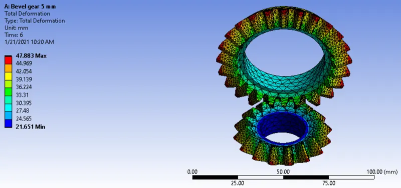
Figure 7: Total Deformation with 5 mm mesh size
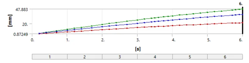
Figure 8: Total Deformation plot with 5 mm mesh size
| Time [s] |
Minimum [mm] | Maximum [mm] | Average [mm] | |
| 1 | 0.2 | 0.87249 | 1.8939 | 1.4199 |
| 2 | 0.4 | 1.7439 | 3.7856 | 2.8426 |
| 3 | 0.7 | 3.0467 | 6.6136 | 4.982 |
| 4 | 1 | 4.3412 | 9.4236 | 7.0755 |
| 5 | 1.2 | 5.1978 | 11.283 | 8.4679 |
| 6 | 1.4 | 6.048 | 13.129 | 9.8656 |
| 7 | 1.7 | 7.3093 | 15.866 | 11.958 |
| 8 | 2 | 8.5505 | 18.561 | 14.002 |
| 9 | 2.2 | 9.3652 | 20.329 | 15.345 |
| 10 | 2.4 | 10.168 | 22.073 | 16.687 |
| 11 | 2.7 | 11.35 | 24.637 | 18.681 |
| 12 | 3 | 12.5 | 27.134 | 20.642 |
| 13 | 3.2 | 13.248 | 28.758 | 21.915 |
| 14 | 3.4 | 13.98 | 30.346 | 23.166 |
| 15 | 3.5 | 14.339 | 31.127 | 23.793 |
| 16 | 3.6 | 14.695 | 31.898 | 24.412 |
| 17 | 3.75 | 15.219 | 33.036 | 25.335 |
| 18 | 3.875 | 15.648 | 33.968 | 26.1 |
| 19 | 4 | 16.07 | 34.883 | 26.861 |
| 20 | 4.2 | 16.728 | 36.312 | 28.03 |
| 21 | 4.4 | 17.366 | 37.698 | 29.18 |
| 22 | 4.6 | 17.983 | 39.037 | 30.31 |
| 23 | 4.8 | 18.579 | 40.329 | 31.423 |
| 24 | 5 | 19.151 | 41.572 | 32.515 |
| 25 | 5.2 | 19.7 | 42.764 | 33.582 |
| 26 | 5.4 | 20.225 | 43.904 | 34.6 |
| 27 | 5.7 | 20.967 | 45.855 | 36.083 |
| 28 | 5.8 | 21.201 | 46.534 | 36.566 |
| 29 | 5.9 | 21.429 | 47.213 | 37.044 |
| 30 | 6 | 21.651 | 47.883 | 37.514 |
Table 4: Total Deformation table with 5 mm mesh size
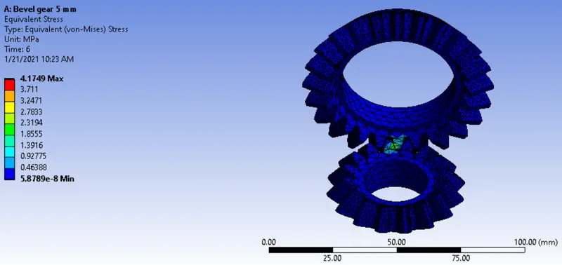
Figure 9: Equivalent Stress with 5 mm mesh size
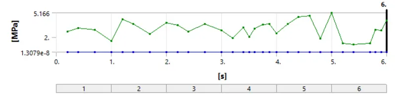
Figure 10: Equivalent Stress plot with 5 mm mesh size
| Time [s] | Minimum [MPa] | Maximum [MPa] | Average [MPa] | |
| 1 | 0.2 | 2.87E-08 | 2.7331 | 1.13E-02 |
| 2 | 0.4 | 1.74E-08 | 3.164 | 1.34E-02 |
| 3 | 0.7 | 1.84E-08 | 2.8986 | 1.22E-02 |
| 4 | 1 | 1.79E-08 | 1.4585 | 9.24E-03 |
| 5 | 1.2 | 2.05E-08 | 4.2867 | 1.25E-02 |
| 6 | 1.4 | 2.18E-08 | 3.7391 | 1.18E-02 |
| 7 | 1.7 | 4.59E-08 | 2.3629 | 1.08E-02 |
| 8 | 2 | 1.72E-08 | 3.8573 | 9.68E-03 |
| 9 | 2.2 | 1.75E-08 | 3.5314 | 1.22E-02 |
| 10 | 2.4 | 2.03E-08 | 2.6755 | 1.15E-02 |
| 11 | 2.7 | 6.44E-08 | 3.676 | 1.39E-02 |
| 12 | 3 | 1.41E-08 | 2.8419 | 1.20E-02 |
| 13 | 3.2 | 1.72E-08 | 1.8842 | 8.96E-03 |
| 14 | 3.4 | 1.58E-08 | 3.2186 | 1.21E-02 |
| 15 | 3.5 | 1.77E-08 | 2.0065 | 9.42E-03 |
| 16 | 3.6 | 1.62E-08 | 3.0559 | 1.16E-02 |
| 17 | 3.75 | 1.50E-08 | 3.6382 | 1.34E-02 |
| 18 | 3.875 | 1.52E-07 | 3.6955 | 1.36E-02 |
| 19 | 4 | 3.78E-08 | 2.4346 | 1.08E-02 |
| 20 | 4.2 | 3.72E-08 | 3.7344 | 1.28E-02 |
| 21 | 4.4 | 3.40E-08 | 4.6338 | 1.33E-02 |
| 22 | 4.6 | 3.24E-08 | 4.7661 | 1.34E-02 |
| 23 | 4.8 | 3.79E-08 | 1.7877 | 8.73E-03 |
| 24 | 5 | 9.31E-08 | 5.166 | 1.51E-02 |
| 25 | 5.2 | 1.31E-08 | 1.1594 | 7.72E-03 |
| 26 | 5.4 | 1.44E-08 | 0.98863 | 7.44E-03 |
| 27 | 5.7 | 1.78E-08 | 1.1724 | 8.55E-03 |
| 28 | 5.8 | 1.78E-08 | 2.926 | 1.16E-02 |
| 29 | 5.9 | 7.38E-08 | 2.8749 | 1.19E-02 |
| 30 | 6 | 5.88E-08 | 4.1749 | 1.33E-02 |
Table 5: Equivalent Stress table with 5 mm mesh size
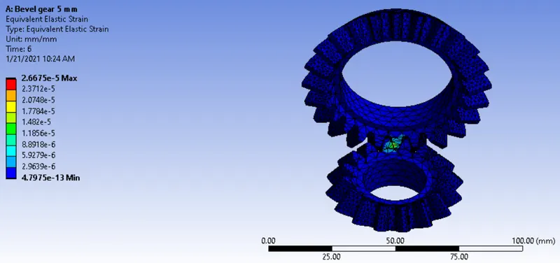
Figure 11: Equivalent Strain with 5 mm mesh size
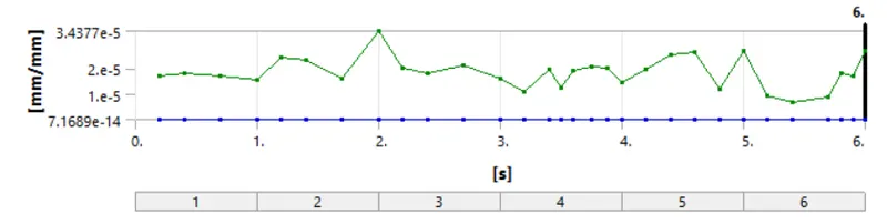
Figure 12: Equivalent Strain plot with 5 mm mesh size
| Time [s] | Minimum [mm/mm] | Maximum [mm/mm] | Average [mm/mm] | |
| 1 | 0.2 | 1.67E-13 | 1.70E-05 | 6.90E-08 |
| 2 | 0.4 | 2.35E-13 | 1.80E-05 | 8.11E-08 |
| 3 | 0.7 | 1.96E-13 | 1.67E-05 | 7.30E-08 |
| 4 | 1 | 2.02E-13 | 1.52E-05 | 5.74E-08 |
| 5 | 1.2 | 1.94E-13 | 2.42E-05 | 7.49E-08 |
| 6 | 1.4 | 1.98E-13 | 2.32E-05 | 7.20E-08 |
| 7 | 1.7 | 2.60E-13 | 1.57E-05 | 6.64E-08 |
| 8 | 2 | 1.82E-13 | 3.44E-05 | 6.23E-08 |
| 9 | 2.2 | 1.67E-13 | 2.03E-05 | 7.39E-08 |
| 10 | 2.4 | 1.70E-13 | 1.81E-05 | 7.08E-08 |
| 11 | 2.7 | 8.17E-13 | 2.09E-05 | 8.45E-08 |
| 12 | 3 | 7.17E-14 | 1.59E-05 | 7.16E-08 |
| 13 | 3.2 | 8.69E-14 | 1.10E-05 | 5.52E-08 |
| 14 | 3.4 | 8.04E-14 | 1.94E-05 | 7.31E-08 |
| 15 | 3.5 | 8.97E-14 | 1.21E-05 | 5.89E-08 |
| 16 | 3.6 | 8.31E-14 | 1.90E-05 | 7.07E-08 |
| 17 | 3.75 | 7.57E-14 | 2.07E-05 | 8.06E-08 |
| 18 | 3.875 | 1.49E-12 | 2.02E-05 | 8.17E-08 |
| 19 | 4 | 2.08E-13 | 1.42E-05 | 6.67E-08 |
| 20 | 4.2 | 2.38E-13 | 1.96E-05 | 7.66E-08 |
| 21 | 4.4 | 2.42E-13 | 2.53E-05 | 8.02E-08 |
| 22 | 4.6 | 2.55E-13 | 2.61E-05 | 8.05E-08 |
| 23 | 4.8 | 2.77E-13 | 1.16E-05 | 5.32E-08 |
| 24 | 5 | 1.13E-12 | 2.69E-05 | 9.07E-08 |
| 25 | 5.2 | 2.35E-13 | 9.40E-06 | 4.78E-08 |
| 26 | 5.4 | 2.42E-13 | 6.76E-06 | 4.57E-08 |
| 27 | 5.7 | 2.21E-13 | 8.59E-06 | 5.27E-08 |
| 28 | 5.8 | 2.00E-13 | 1.81E-05 | 7.02E-08 |
| 29 | 5.9 | 8.99E-13 | 1.70E-05 | 7.12E-08 |
| 30 | 6 | 4.80E-13 | 2.67E-05 | 8.02E-08 |
Table 6: Equivalent Strain table with 5 mm mesh size
Case 3: 4mm mesh size
- Setup: A new Static Structural study was created in ANSYS Workbench.
- Boundary conditions: Structural steel was applied as the material.
- Frictional contact is established between the small and the large gear.
- The gears are secured using revolute joints.
- Mesh: A mesh size of 4 mm is chosen for all bodies and then a finer mesh of 1.75 mm is chosen for certain surfaces where refinement is required using face sizing.
- Loads: A moment of 100 Nmm was applied and an angular displacement of 120mm in 6 steps was defined to replicate the rotation of the gears.
- Results: The mesh is generated and Stress, Strain, and Deformation are chosen as the solutions to be evaluated. The results are tabulated in the results section of the report.
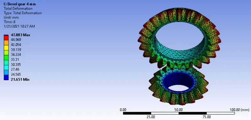
Figure 13: Total Deformation with 4 mm mesh size
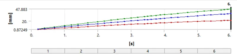
Figure 14: Total Deformation plot with 4 mm mesh size
| Time [s] |
Minimum [mm] | Maximum [mm] | Average [mm] | |
| 1 | 0.2 | 0.87249 | 1.8939 | 1.4064 |
| 2 | 0.4 | 1.7439 | 3.7856 | 2.8156 |
| 3 | 0.7 | 3.0467 | 6.6136 | 4.9349 |
| 4 | 1 | 4.3412 | 9.4236 | 7.0084 |
| 5 | 1.2 | 5.1978 | 11.283 | 8.3876 |
| 6 | 1.4 | 6.048 | 13.129 | 9.7721 |
| 7 | 1.7 | 7.3093 | 15.866 | 11.845 |
| 8 | 2 | 8.5505 | 18.561 | 13.87 |
| 9 | 2.2 | 9.3652 | 20.329 | 15.2 |
| 10 | 2.4 | 10.168 | 22.073 | 16.529 |
| 11 | 2.6 | 10.959 | 23.79 | 17.848 |
| 12 | 2.8 | 11.737 | 25.477 | 19.163 |
| 13 | 3 | 12.5 | 27.134 | 20.447 |
| 14 | 3.2 | 13.248 | 28.758 | 21.709 |
| 15 | 3.4 | 13.98 | 30.346 | 22.948 |
| 16 | 3.5 | 14.339 | 31.127 | 23.569 |
| 17 | 3.6 | 14.695 | 31.898 | 24.183 |
| 18 | 3.75 | 15.219 | 33.036 | 25.098 |
| 19 | 3.875 | 15.648 | 33.968 | 25.856 |
| 20 | 4 | 16.07 | 34.883 | 26.61 |
| 21 | 4.2 | 16.728 | 36.312 | 27.769 |
| 22 | 4.4 | 17.366 | 37.698 | 28.908 |
| 23 | 4.7 | 18.284 | 39.689 | 30.581 |
| 24 | 5 | 19.151 | 41.572 | 32.213 |
| 25 | 5.2 | 19.7 | 42.764 | 33.271 |
| 26 | 5.4 | 20.225 | 43.904 | 34.281 |
| 27 | 5.7 | 20.967 | 45.855 | 35.751 |
| 28 | 5.8 | 21.201 | 46.534 | 36.23 |
| 29 | 5.9 | 21.429 | 47.213 | 36.704 |
| 30 | 6 | 21.651 | 47.883 | 37.171 |
Table 7: Total Deformation table with 4 mm mesh size
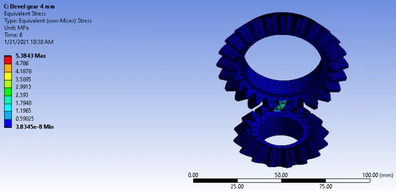
Figure 15: Equivalent Stress with 4 mm mesh size
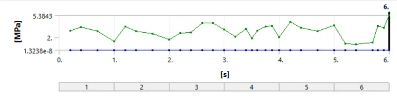
Figure 16: Equivalent Stress plot with 4 mm mesh size
| Time [s] | Minimum [MPa] | Maximum [MPa] | Average [MPa] | |
| 1 | 0.2 | 1.89E-08 | 2.9691 | 1.08E-02 |
| 2 | 0.4 | 2.99E-08 | 3.5139 | 1.29E-02 |
| 3 | 0.7 | 2.05E-08 | 2.8939 | 1.17E-02 |
| 4 | 1 | 1.84E-08 | 1.401 | 8.92E-03 |
| 5 | 1.2 | 2.29E-08 | 3.6063 | 1.17E-02 |
| 6 | 1.4 | 2.35E-08 | 2.9494 | 1.12E-02 |
| 7 | 1.7 | 5.20E-08 | 2.5708 | 1.02E-02 |
| 8 | 2 | 1.46E-08 | 1.6464 | 8.72E-03 |
| 9 | 2.2 | 2.03E-08 | 2.6424 | 1.13E-02 |
| 10 | 2.4 | 2.49E-08 | 2.7542 | 1.08E-02 |
| 11 | 2.6 | 3.10E-08 | 4.2028 | 1.26E-02 |
| 12 | 2.8 | 5.92E-08 | 4.2102 | 1.30E-02 |
| 13 | 3 | 1.59E-08 | 3.2058 | 1.16E-02 |
| 14 | 3.2 | 1.32E-08 | 2.0739 | 8.77E-03 |
| 15 | 3.4 | 2.09E-08 | 3.2896 | 1.17E-02 |
| 16 | 3.5 | 1.58E-08 | 1.8285 | 9.23E-03 |
| 17 | 3.6 | 2.15E-08 | 3.0516 | 1.12E-02 |
| 18 | 3.75 | 1.50E-08 | 3.6402 | 1.29E-02 |
| 19 | 3.875 | 1.52E-07 | 3.6972 | 1.31E-02 |
| 20 | 4 | 4.02E-08 | 2.0274 | 1.04E-02 |
| 21 | 4.2 | 3.70E-08 | 4.3732 | 1.22E-02 |
| 22 | 4.4 | 3.69E-08 | 3.4684 | 1.22E-02 |
| 23 | 4.7 | 3.65E-08 | 2.8919 | 1.16E-02 |
| 24 | 5 | 1.20E-07 | 3.8768 | 1.39E-02 |
| 25 | 5.2 | 2.82E-08 | 1.0241 | 7.51E-03 |
| 26 | 5.4 | 2.93E-08 | 0.87847 | 7.25E-03 |
| 27 | 5.7 | 2.93E-08 | 1.2209 | 8.22E-03 |
| 28 | 5.8 | 2.65E-08 | 3.7525 | 1.13E-02 |
| 29 | 5.9 | 6.70E-08 | 3.5052 | 1.15E-02 |
| 30 | 6 | 3.83E-08 | 5.3843 | 1.29E-02 |
Table 8: Equivalent Stress table with 4 mm mesh size
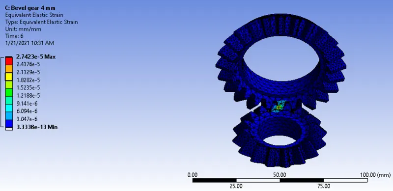
Figure 17: Equivalent Strain with 4 mm mesh size
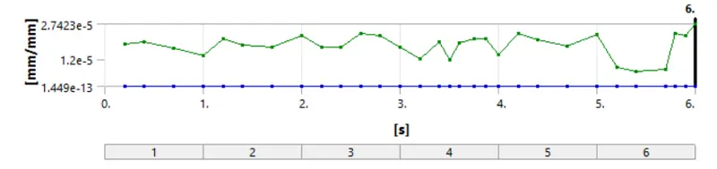
Figure 18: Equivalent Strain plot with 4 mm mesh size
| Time [s] | Minimum [mm/mm] | Maximum [mm/mm] | Average [mm/mm] | |
| 1 | 0.2 | 1.80E-13 | 1.84E-05 | 6.56E-08 |
| 2 | 0.4 | 2.13E-13 | 1.94E-05 | 7.73E-08 |
| 3 | 0.7 | 2.28E-13 | 1.67E-05 | 6.97E-08 |
| 4 | 1 | 2.47E-13 | 1.36E-05 | 5.51E-08 |
| 5 | 1.2 | 2.31E-13 | 2.11E-05 | 7.06E-08 |
| 6 | 1.4 | 2.38E-13 | 1.83E-05 | 6.75E-08 |
| 7 | 1.7 | 4.11E-13 | 1.72E-05 | 6.32E-08 |
| 8 | 2 | 1.58E-13 | 2.25E-05 | 5.55E-08 |
| 9 | 2.2 | 1.45E-13 | 1.71E-05 | 6.77E-08 |
| 10 | 2.4 | 1.50E-13 | 1.71E-05 | 6.51E-08 |
| 11 | 2.6 | 1.84E-13 | 2.33E-05 | 7.53E-08 |
| 12 | 2.8 | 6.95E-13 | 2.22E-05 | 7.71E-08 |
| 13 | 3 | 1.86E-13 | 1.72E-05 | 6.88E-08 |
| 14 | 3.2 | 2.09E-13 | 1.23E-05 | 5.40E-08 |
| 15 | 3.4 | 1.93E-13 | 1.93E-05 | 7.06E-08 |
| 16 | 3.5 | 2.11E-13 | 1.15E-05 | 5.70E-08 |
| 17 | 3.6 | 2.02E-13 | 1.90E-05 | 6.81E-08 |
| 18 | 3.75 | 1.81E-13 | 2.08E-05 | 7.72E-08 |
| 19 | 3.875 | 1.45E-12 | 2.07E-05 | 7.83E-08 |
| 20 | 4 | 2.50E-13 | 1.42E-05 | 6.36E-08 |
| 21 | 4.2 | 2.29E-13 | 2.33E-05 | 7.29E-08 |
| 22 | 4.4 | 2.36E-13 | 2.05E-05 | 7.41E-08 |
| 23 | 4.7 | 2.48E-13 | 1.78E-05 | 7.09E-08 |
| 24 | 5 | 1.13E-12 | 2.28E-05 | 8.31E-08 |
| 25 | 5.2 | 2.63E-13 | 8.50E-06 | 4.60E-08 |
| 26 | 5.4 | 2.66E-13 | 6.60E-06 | 4.39E-08 |
| 27 | 5.7 | 2.38E-13 | 7.66E-06 | 4.97E-08 |
| 28 | 5.8 | 2.14E-13 | 2.34E-05 | 6.81E-08 |
| 29 | 5.9 | 9.63E-13 | 2.21E-05 | 6.89E-08 |
| 30 | 6 | 3.33E-13 | 2.74E-05 | 7.74E-08 |
Table 9: Equivalent Strain table with 4 mm mesh size
Results
What is grid dependency?
As a fundamental rule in FEA, the finer the mesh the more accurate the result. This rule comes with certain conditions. If the mesh is too coarse, then the results are fairly inaccurate when compared to those of a fine mesh. However, having an overly fine mesh means excessive processing times. When the mesh goes from coarse to fine, it reaches a point of refinement where the difference between the previous mesh and the current mesh is almost zero. The process of determining this optimum mesh by going from coarse to fine is called the grid dependency test.