Bevel Gear Challenge
- Objectives: To perform a Grid Dependency Test on Bevel Gear to get optimum results
- Geometrical Design:
We are having a Bevel Gear assembly which will be used to analyse for FEA, take a look at geometry below
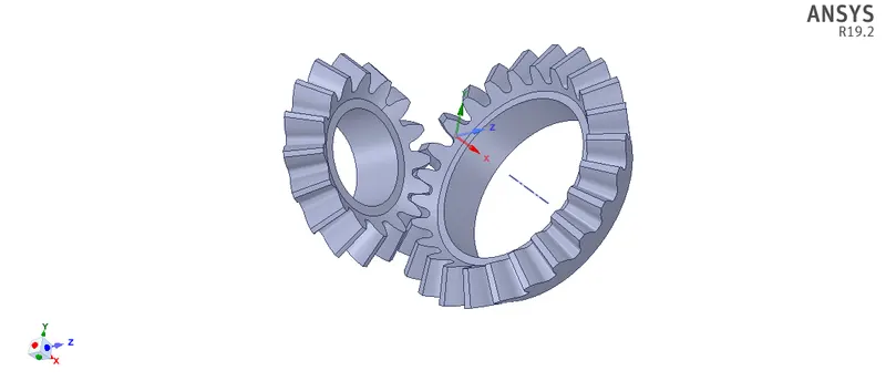
As we are working for Grid Dependency, we also focussed on Geometry Clean up, the inner solid portion is removed so that mesh density will reduce and will lead to less computational time.
- Material Properties:
We have taken Structural Steel as material for Bevel Gears;

- Problem Statement
Bevel Gear Assembly is analysed with ANSYS Workbench for FEA to obtain Grid Dependency.
Considering the analysis point of view, we will work for 3 cases in this project, we will try to analyse three different sizes of mesh, 1) 5 mm, 2) 4 mm, 3) 3 mm. Gears are named as per their size Small Gear & Big Gear.
Before checking the Analysis results, let’s have some briefing about GRID DEPENDENCY
What is Grid Dependency?
- Grid Dependency is the method used in CAE to get optimum results by reducing mesh density in a given component.
- Grid Dependency, Mesh Refinement or Scaling are similar words used in FEA & CFD analysis.
- Initially, FEA process starts with the Default or Coarse Mesh after obtaining the results, a mesh is refined in areas of interest which will give appropriate results.
- This process is followed until the user gets optimised results for a given problem. When there is no significant change in Equivalent Stress and Equivalent Elastic Strain we can say that the mesh refinement is achieved, further mesh refinement will not show drastic change in values of Stress and Strain.
- When the mesh size becomes smaller it will lead to higher computational time. There can be an issue with Force Convergence as well.
- The results obtained by mesh refinement give accurate result close to realistic results.
- Grid Dependency means not only reduction of mesh size, but we can achieve it by Linear or Quadric Elements, it also depends on Geometry as well.
- Boundary Conditions:
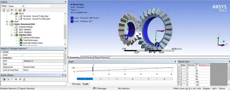
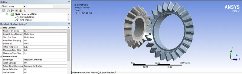
Both the gears provided with Friction and Joint Contacts. Analysis is carried out in 6 steps; Small Gear is applied with joint rotation up to 1200 and Big Gear is constrained with 100 N-mm moments in each step.
Have look at constraints
- Analysis:
Case: 1 (Mesh Size 5 mm)
- Mesh Criterion:
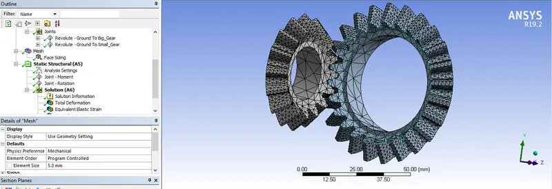
In this analysis we kept 5mm mesh on Gear Body and on the Gear Teeth we kept 1.75 mm mesh.
- Analysis Settings:
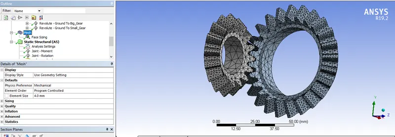
Case: 2 (Mesh Size 4 mm)
- Mesh Criterion:
In this analysis we kept 4 mm mesh on Gear Body and on the Gear Teeth we kept 1.75 mm mesh
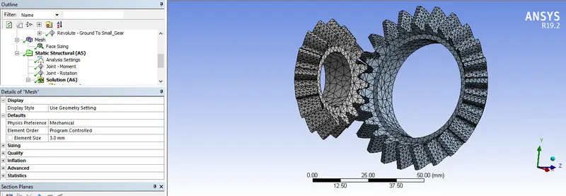
Case: 3 (Mesh Size 3 mm)
- Mesh Criterion:
In this analysis we kept 3 mm mesh on Gear Body and on the Gear Teeth we kept 1.75 mm mesh
- Post Processing:
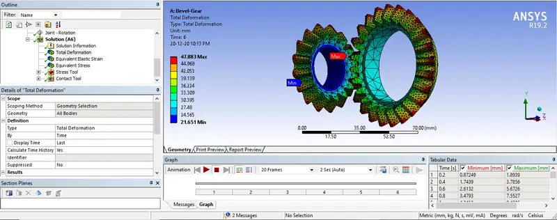
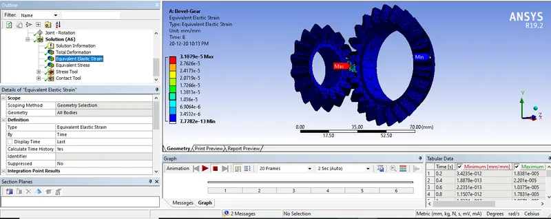
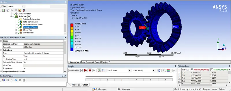
- Case: 1 (Mesh Size 5 mm)
Total Deformation:
Equivalent Elastic Strain:
Equivalent Stress:
- Case: 2 (Mesh Size 4 mm)
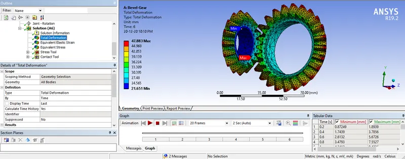
Total Deformation:
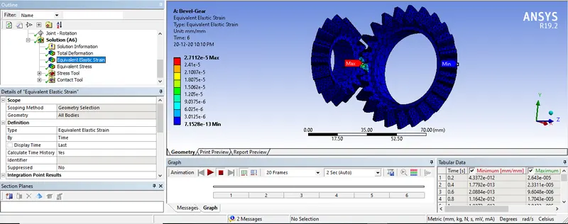
Equivalent Elastic Strain:
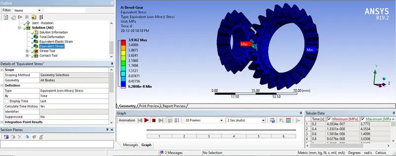
Equivalent Stress:
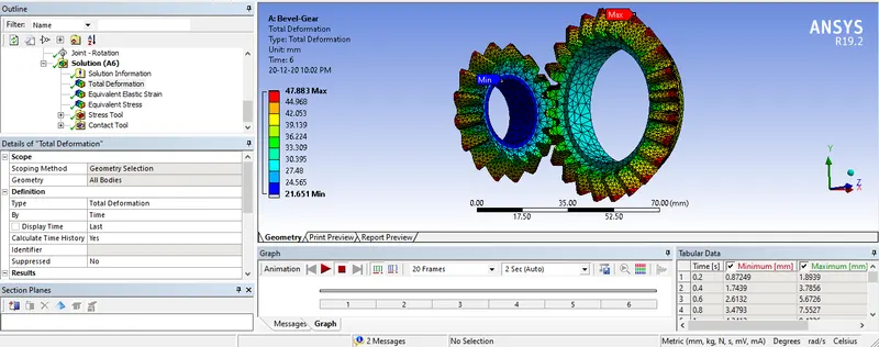
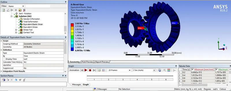
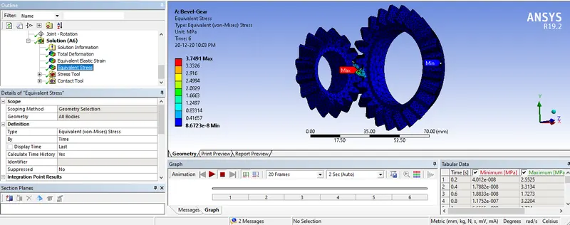
- Case: 3 (Mesh Size 3 mm)
Total Deformation:
Equivalent Elastic Strain:
Equivalent Stress:
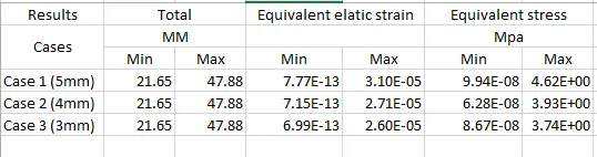
Post Process Results Summary;
- Results and Conclusion:
1) Total Deformation is Similar in all three cases.
2) The values of Equivalent Elastic Strain is decreasing when we decrease the mesh size, there is a small change in values of strain.
3) Same as strain, Equivalent Stress value also changes with the mesh size.
We can clearly see that the result obtained with 3 mm mesh is a bit similar to 5 mm mesh so we can say that 3 mm mesh results are accurate and close to realistic results.