Week 2 Bevel Gear Challenge
OBJECTIVE
To do a grid dependancy simulation test on the model at the mesh sizes of 6 mm, 5mm, and 4mm on a meshed bevel gear pair and postprocess the results obtaind.
Grid Dependancy Test
Grid dependency test is to investigate how the solution depends on the grid size by running the simulation with refined mesh that is finer the mesh, higher is the accuracy of the result but with additional cost on computation time and computational power. Since, solutions are interpolated at the nodes to get an approximate result, higher the number of nodes and elements higher is the computational time and power required to complete the simulation.So, the grid dependency test helps in determining optimal mesh size where the accurate result could be obtained keeping in the mind the cost of time and power. Since the result obtained are approximate, Refining mesh further would result in negligible per cent change is the result but only increase the computational cost.
CASE SETUP
In the ansys workbench , from the engineering sources add the Structural Steel material into the library.
Then we can insert the CAD model of the Bevel gear meshed and then we can assign structural steel on the bevel gear.
Next in the mechanical modeller , in contact region we set rename based on defiination and then in contacts we set with formulation as augmented langrange which is less sensitive to the stiffness of the conatct and have better convergance. And we set the contacts as frictional
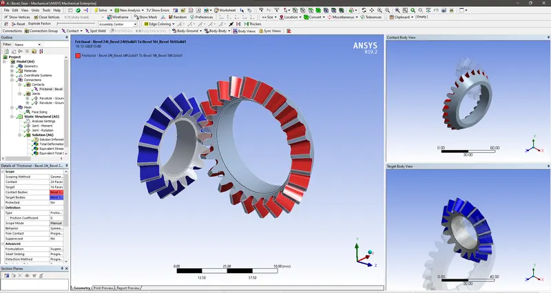
Contacts Created between the tooth of the bevel gear pair
Then we need to mesh the bevel gear model , for that we can add a method and set the element type as tetrahedrons and then insert a sizing of element size as a parameter. As we needs to vary the value of thus and we need to check the output . So in the solution also we needs to set some solution parameters as parameters.
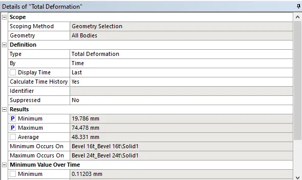
Parameter is defined on the maximum and minimum values of the solution paramters
Next is the setting up of the analysis settings .In that set steps as 6 and select all those steps and switch ON auto timestepping, Then define by time and set the intial time step,minimum time step and maximum timestep.Intial time step is made low so that the solver will run through first set of iteration without any errors as the possibility of the contacts happening in the model will be less.
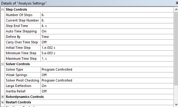
Analysis Settings
As we have gear joints which is having the rotation along an axis which is same as the revolute joint, we need to create the revolute joints to get the rotation about the axis. So create two joints and set the scope by selecting the inner faces of the gear .If the dof applied is not in the direction of the cordinate system axis , change the axis manually and make it alligned with the dof.
Revolute Joint Created on Smaller gear
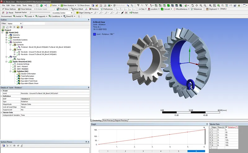
Revolute Joint on the Bigger Gear
Then what we need to do is to create a joint load on those two joints.On the left gear , we can give the rotation along the free axis by giving rotation in angles in steps. Here we decided to have 6 steps and we dvide the 180 degree rotation in 6 steps.Each rotation is about 30 degeres each.
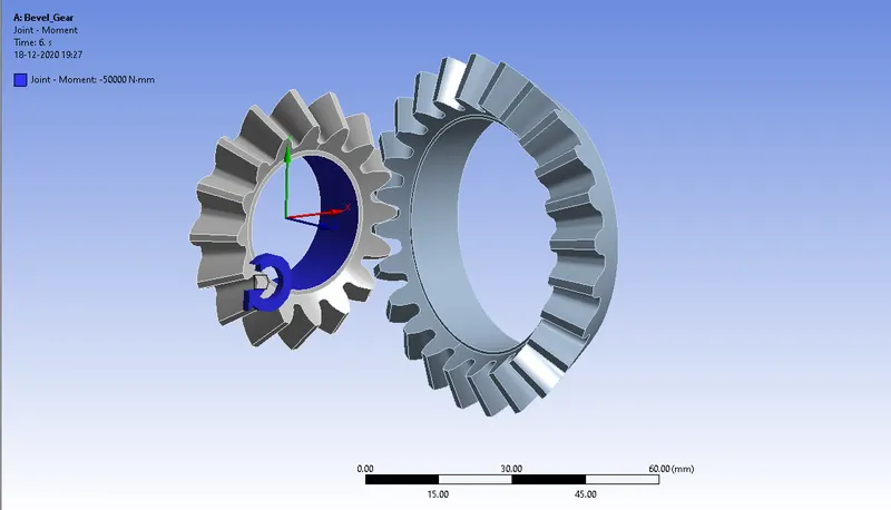
In the other joint we set a joint load with the moment as a tabular colum an chech the rotation direction of the gears and chech whether it makes sense , if not reverse the direction by changing the sign of the magnitude of the moments.
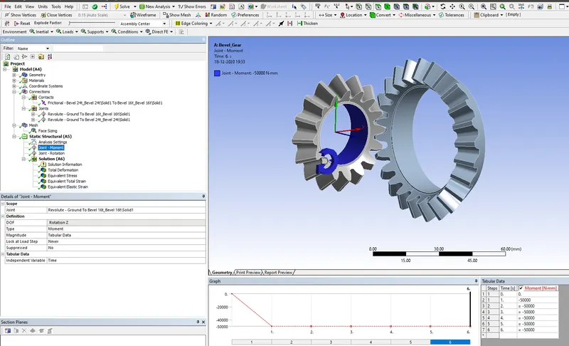
Joint Load in the form of Moment is applied over the smaller gear
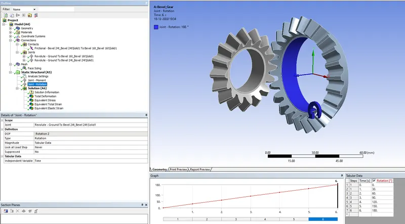
Joint Load in the form of Rotation is applied over the Bigger Gear
Then rest is we need to request for the solutions such as the Directional stress in Y axis, Von mises stress and Von mises strain.In very solution we need to set the maximum value and minimum value as parameter.
RESULTS
Case 1 : With 6 mm Mesh
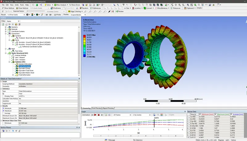
Total Deformation on Bevel gear
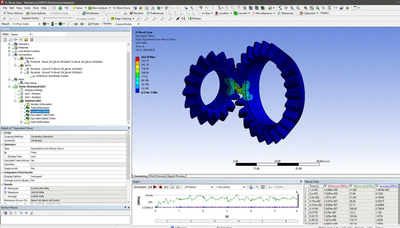
Equivalent Stress
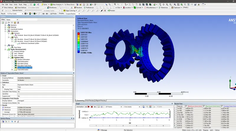
Equivalent Strain
Case 3 : With 5 mm Mesh
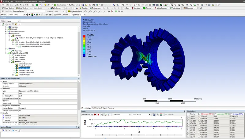
Equivalent Stress
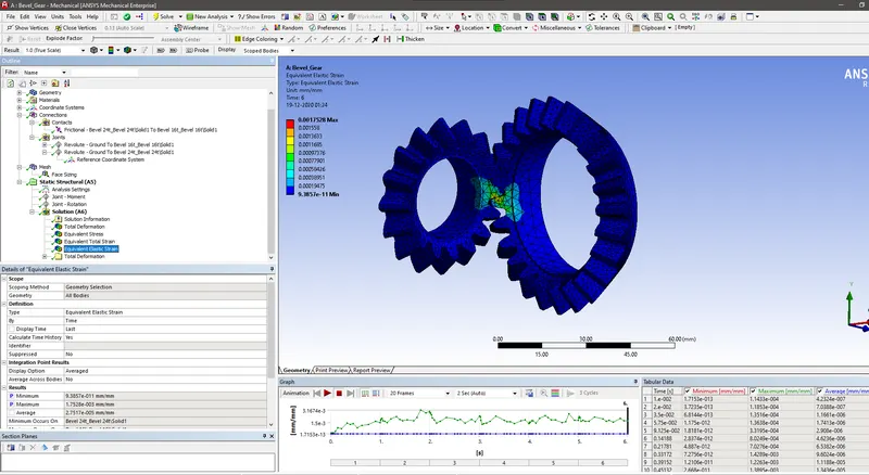
Equivalent Elastic Strain
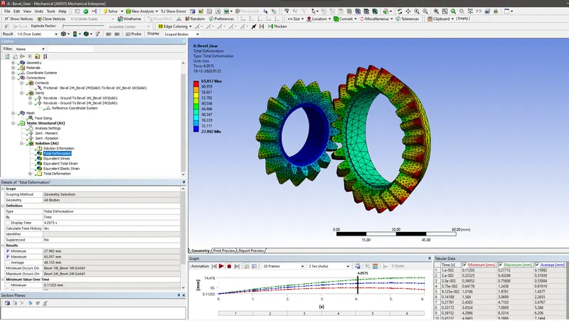
Total Deformation
Case 3 : With 4 mm Mesh
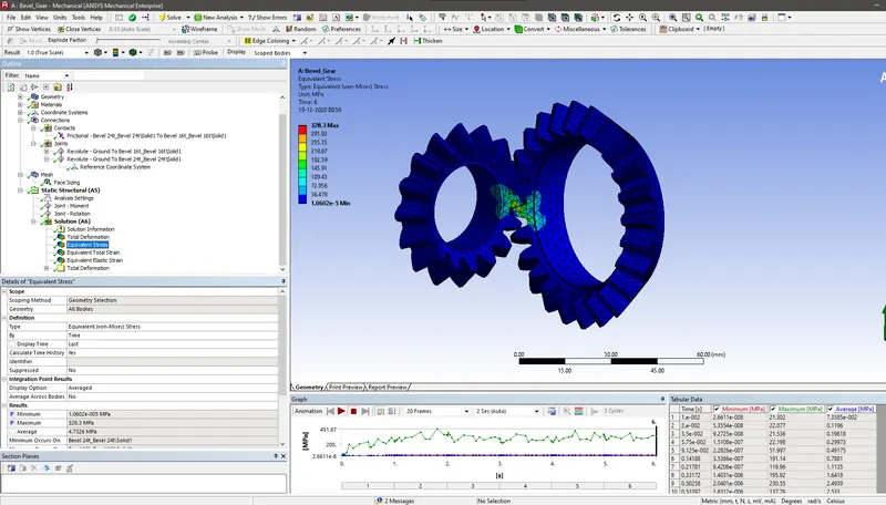
Equivalent Stress
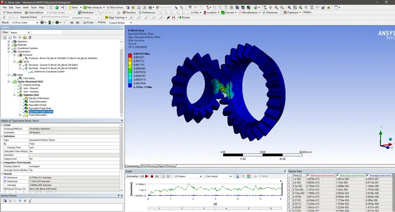
Equivalent Elastic Strain
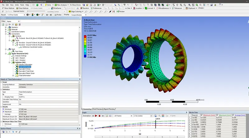
Total Deformation

Design Points and its requested parameters value
| Equivalent Elastic Stress | Equivalent Elastic Strain | Total Deformation | |
| Mesh size 4 mm | 328.3 Mpa | 0.0017361 | 65.057 mm |
| Mesh size 5 mm | 305.5 Mpa | 0.0017528 | 65.057 mm |
| Mesh size 6 mm | 264.50 Mpa | 0.0017561 | 65.057 mm |
Conclusion
As the mesh size decreases the number of integration points and number of nodes increased and so that the accuracy of the result will be increased.So as the mesh size decreased from 6 mm to 4mm the result getting more and more closer to the actual value.Her the stress value is more accurate in 4 mm mesh size. The cor=arse mesh gives the stress as 264.5 Mpa and when the mesh is more fine, the stress value is 328.3 Mpa.So the acceptable value is 328.If we still reduce the mesh value and the changes in result is limited from the previous mesh size value, then we can fix that mesh size.