Week 2 : Basic Calibration of Single cylinder SI-Engine
AIM
* To run the single cylinder SI engine case setup at 1800 rpm and to list down important parameters such as air flow rate, BSFC, BMEP, In cylinder pressure.
* To run the same case setup at 3600 rpm and increase the output power by 10%.
INTRODUCTION
Single cylinder SI case setup is a tutorial available in the GT-suite, this tutorial is opened up and local controls are changed to fulfill the requirements. When the tutorial case is opened at first we will see the project map as shown below,
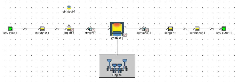
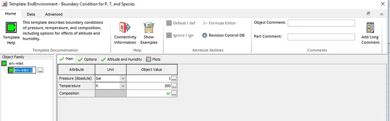
* First comes the env-inlet-1, this reference object specifies the environment/surrounding from where the air enters into the engine. Temperature and pressure of air entering into the engine is specified for the env-inlet-1.
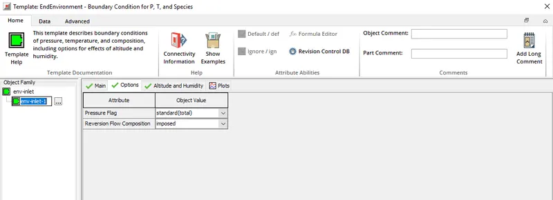
* Also under the options tab pressure flag is imposed as standard and reversion flow composition is set as imposed.
* Intake runner is set as a circular pipe, in the project map this is represented as intrunner-1. Inlet diameter and outlet diameter is set as 40 mm, also the length of the intake runner pipe is set as 350 mm and discretization length is set as 40 mm. If explicit solver is used to run the simulation then setting up the discretizaton length helps in the calculation of the time interval `Delta t`.
* `Delta t prop (Deltax)/(v*abs(u))`, this is the condition used in the calculation of `Delta t`for explicit solver and `Deltax` is the discretization length, `v` is the velocity of the fluid, `abs(u) -` velocity of sound.
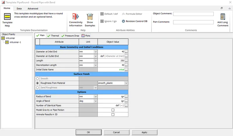
* Initial state implies the initial conditions set for the intake runner, temperature is set at 300 K and pressure is set at 1 bar. Smooth plastic is set as the intake runner material.
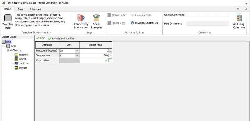
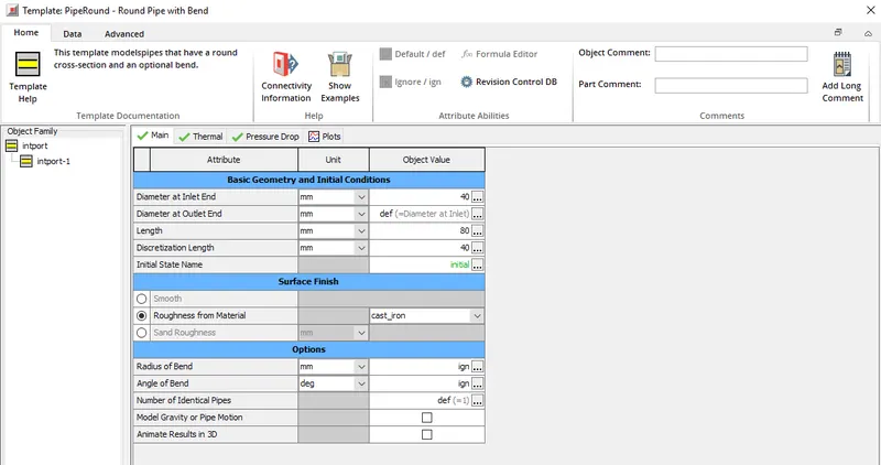
* After the intake runner (intrunner-1) next comes the intake port which is represented as intport-1 in the project map. For intake port as well the inlet and outlet diameter is set to 40 mm, but discretization length is different, for a length of 80 mm discretization length of 40 mm is set. Initial condition is same as 300 K and 1 bar pressure. Material for intake port is set as cast iron.
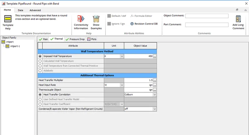
* Under thermal tab the imposed wall temperature is set as 450 K, wall heat transfer model is set as colburn. Apart from these other attributes are ignored.
* Attributes under pressure drop tab are ignored as well.
* Since this is a spark ignition engine the fuel is sprayed into the intake port, where the mixing of the air and fuel takes place before making into the engine cylinder. Si-inject-1 represnts the injector in the project map. Attributes that are set are disscussed below,
* Injector delivery rate is set as 6 g/s, fuel ratio specification is set as air-to-fuel and this ratio is set as 14.5, number of injectors per sensor is set as 1.
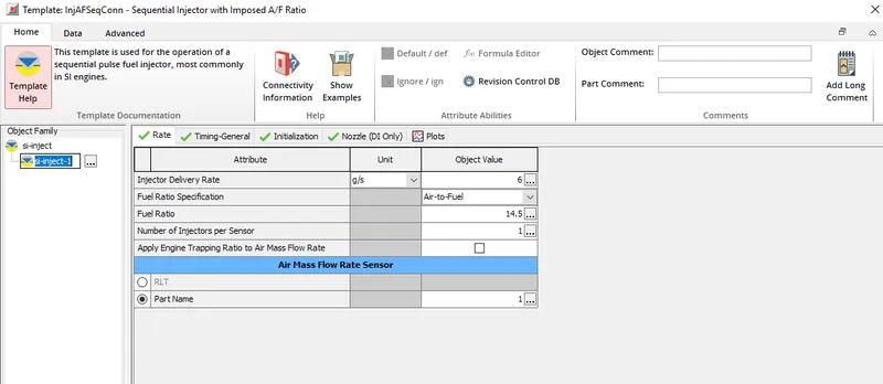
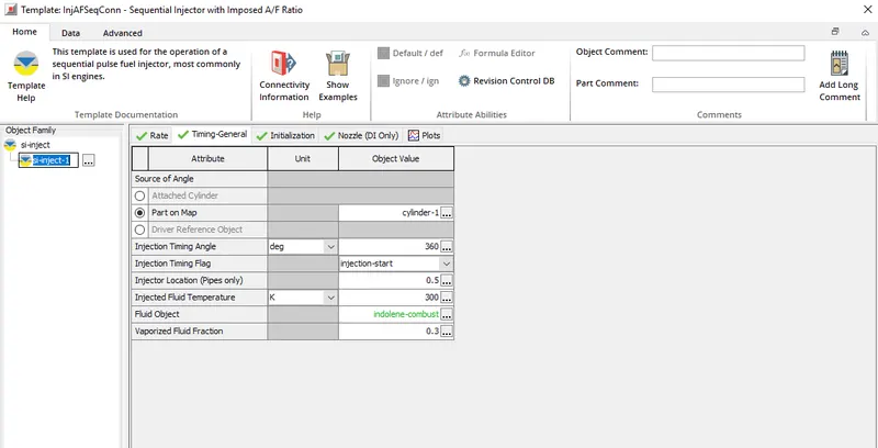
* Next comes the timing related attributes. First attribute is source of angle for which parts on map is selected and cylinder-1 is assigned as part for this attribute. It is at this specified part the air-to-fuel ratio calculations take place.
* Injection timing angle is set as 360 degree, this angle defines the angle at which injection should start. Two options are available, either we can set the injection start or injection end in the injection flag option. If injection start is set as injection flag then the timing angle to be defined is the angle at which the injection starts, if injection flag is set as injection end then the timing angle to be defined is the injection end angle.
* Since the fuel is injected into the the intake port, where exactly the injector is placed or at which location in the intake port injection shall happen is to set. Injection location attribute is set as 0.5 i.e, exactly at middle of the intake port the injection shall take place. A value of 0 to 1 can be set for this attribute.
* Next attribute is the injection fluid temperature which is set at 300 K.
* The fluid which needs to be injected through the injector needs to be set at fluid object attribute, indolene-combust is the fuel object set for this simulation.
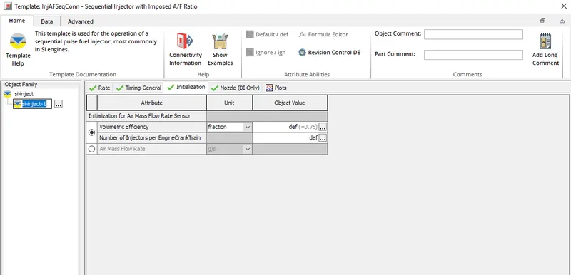
* Next is the initialization tab, where the volumetric efficiency of the engine is set to 0.75, also the number of injectors per engine cranktrain needs to be set, this attribute is set as default so that no of part so injector on the project map will be used as the injector count per engine crank train.
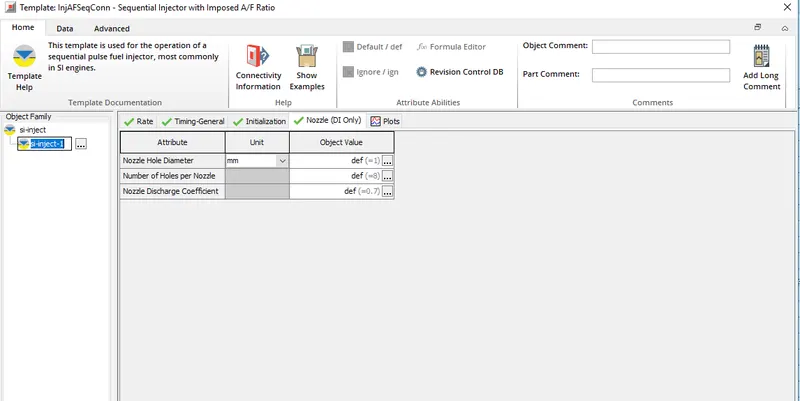
* Next tab is nozzle DI, under which first comes the nozzle hole diameter attribute which is set as 1 mm. Number of holes per nozzle is set as 8 and the nozzle discharge coefficient is set as 0.7.
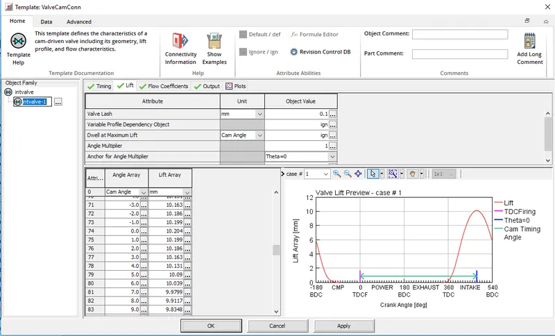
* Next on the project map is the intake valve. First attribute under timing tab is cam timing angle which is set as 239 degree. Cam timing anchor reference is set as TDC firing and Cam timing lift array reference is set as theta = 0.
* Next tab is the lift where the lift profile of the intake valve is defined, for cam angle ranging from -73 degree to 83 degree the valve lift is defined. The max lift of 10.204 mm takes place at 0 degree. A snip of the same is provided below,
* After intake valve the next part is engine cylinder which is defined as cylinder-1 in the project map. First comes the main tab under which the first attribute is initial state object, which defines the initial condition of the fluid inside the cylinder part, a temperature of 300 K and pressure of 1 bar is defined and the fluid composition is set as air.
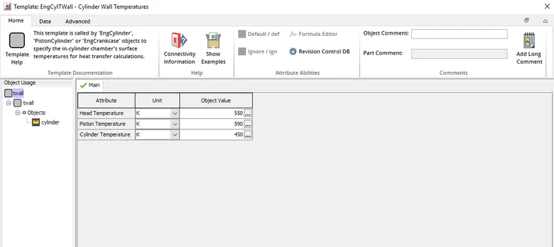
* second attribute under the main tab is wall temperature defined by the reference object, twall is the object value set, where we can set the Head temperature, cylinder temperature and piston temperature. For this simulation these temperature data was not available and hence the temperature of these objects were set as per the reccomended values from GT-suite help. Values of temperature set is shown below,
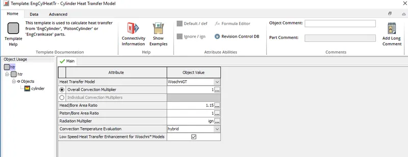
* Third attribute is heat transfer object for which the object value is set as htr. If we open the object value another set of attributes which are disscussed below,
1. Heat transfer model - Here we need to specify a model which is used to calculate the heat transfer coefficient of engine cylinder. WoschniGT model is used, if swirl data is not available then this model is a good to go option.
2. Overall convection multiplier is set to 1.
3. Head/Bore area ratio - ratio of cylinder head surface area to cylinder bore cross sectional area. This attribute is set to 1.15.
4. Piston/Bore area ratio - ratio of piston surface area to cylinder bore cross sectional area, this is set to 1.
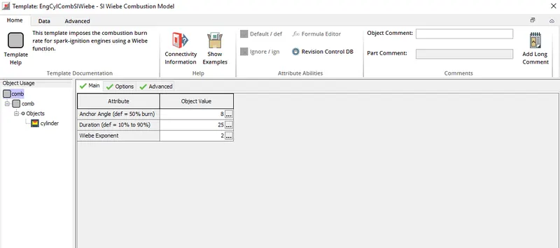
5. Object value of combustion object attribute is set as comb, this defines the combustion model used in the simulation. In this SI wiebe combustion model is used and hence setting up the this attribute as comb invokes this combustion model and hence combustion calculations are computed. There are certain attributes under the comb object value that corresponds to setting up different parameters of the SI wiebe combustion model.
* Under the main tab first attribute is anchor angle this defines the angle of degrees from TDC to 50% combustion in the wiebe curve, which is set as 8.
* 2nd attribute under main tab is duration in which the time taken for 10% to 90% combustion is set, for this simulation it is set as 25 degrees and the GT-power recommends a duration angle 25-35 degrees.
* Wiebe exponent is set as 2.
* Under the options tab there are attributes corresponding to fuel burning all of which are set to default values.
* Under the advanced tab there are attributes which belongs to the emission characteristics all of those are ignored since emission is not modeled.
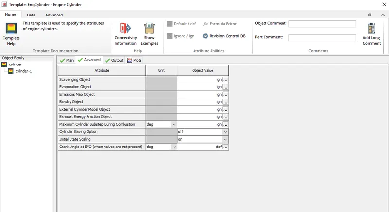
* Certain attributes which corresponds to scavenging, evaporation etc which come under advanced options of engine cylinder part are ignored. A snip of the same is shown below,
* Next part is the engine under which there are attributes pretaining to engine stroke, firing order etc which is disscussed below,
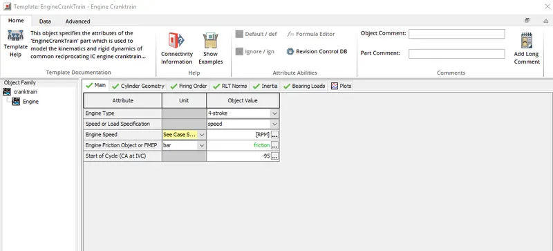
* First comes the main tab under which the first attribute is engine type, two options are available 2-stroke or 4-stroke. Since this is 4 stroke engine we can select the same as object value.
* Next attribute is spped/load specifications, for this the object value we can set either as speed or load. For this simulation speed is set.
* Since the above attribute is set as speed, we need to mention the speed of engine in RPM. For this simulation engine speed is used as parameter and hence for this object value [RPM] is set.
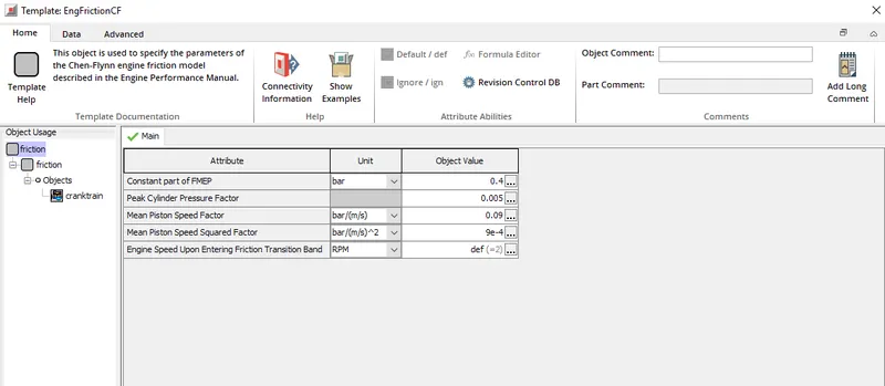
* 4th attribute is engine friction object or FMEP for which the object value is set as friction and inside this object value there are set of attributes regarding the friction which needs to be set.
* Start of cycle is set as -95 degree. A snip of attributes belonging under main tab is shown below,
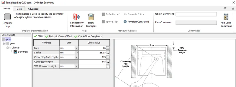
* Next is cylinder geometry tab, here different cylinder geometry such as stroke length, bore value etc are set.
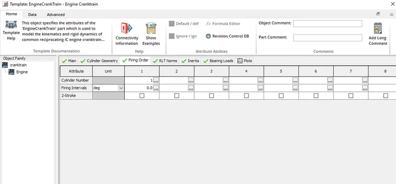
* Next tab is firing order, for this simulation since only 1 cylinder so firing order is set only to this cylinder.
* Other tab are RLT norms, inertia bearing loads. Most of the attributes under these tabs are ignored and some of the attributes are set to default values as per recommended values from GT-power help.
* Next on the project map is the exhaust valve, in project map it is defined as exhvalve-1. First attribute under timing tab is cam timing angle which is set as 126 degree. Cam timing anchor reference is set as TDC firing and Cam timing lift array reference is set as theta = 0.
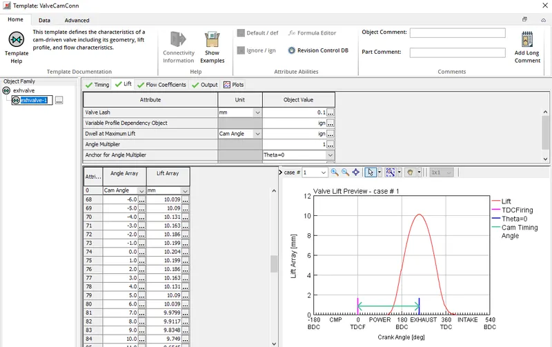
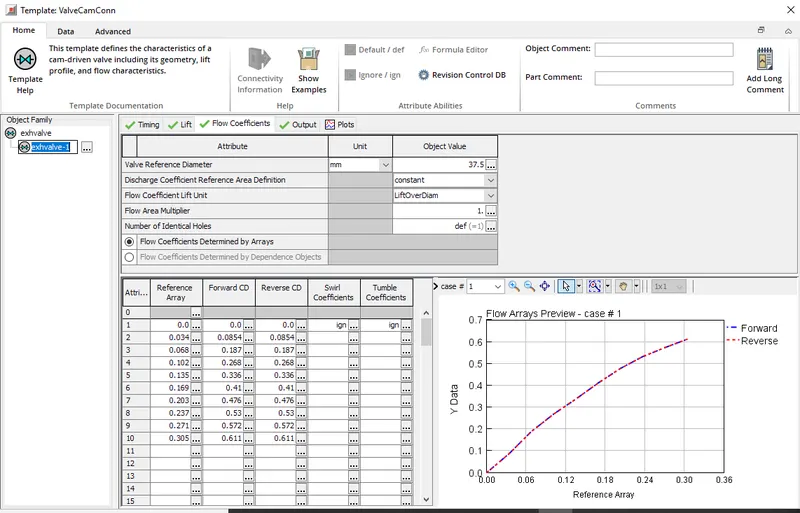
* Next tab is the lift where the lift profile of the exhaust valve is defined, for cam angle ranging from -73 degree to 83 degree the valve lift is defined. The max lift of 10.204 mm takes place at 0 degree. A snip of the same is provided below,
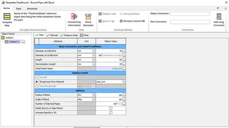
* Next part in the map is exhaust port which is shown as exhport-1 in the map, just like intake port we have to define the inlet diameter, outlet diameter. Inlet diameter is set to 30 mm and same has been defined for outlet as well. Length of the exhaust port is set to 60 mm and discretization length to 55 mm. Material of the exhaust port is defined as cast iron.
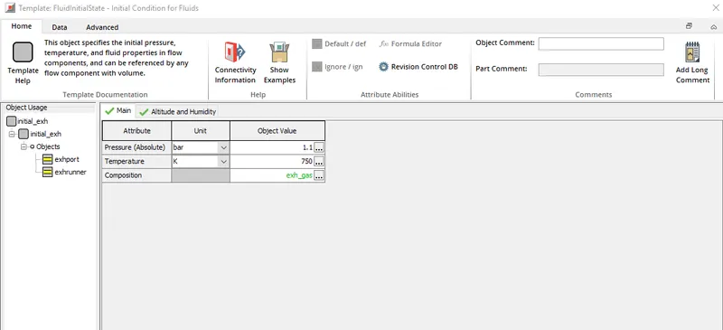
* Initial conditions set for the exhaust port is different from that of intake port. Temperature of 750 K and pressure of 1.1 bar is set and composition of the fluid is set as exhaust.
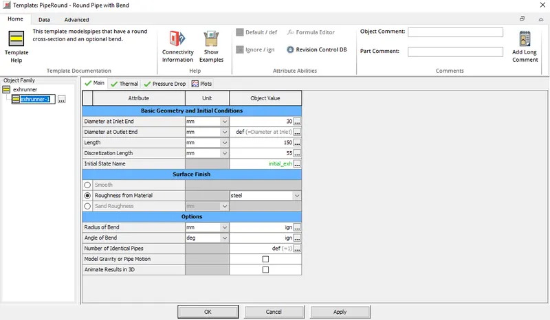
* Next part after exhaust port is exhaust runner which is shown in the project map as exhrunner-1. Inlet and outlet diameter of the exhaust runner is set to 30 mm same as inlet and outlet diameter of exhaust port. Length is set to 150 mm and discretization length to 55 mm. Exhaust runner material is set as steel.
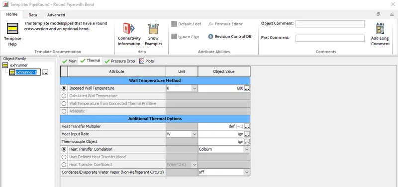
* Under thermal tab the imposed wall temperature is set to 600 K and wall heat transfer model is set to colburn.
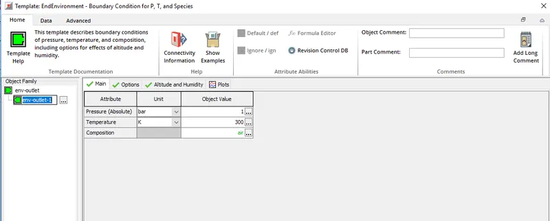
* Last part in the project map is env-outlet-1, this represents the environment into which the exhaust gases move into and hence the pressure is set to 1 bar and temperature is set to 300 K
* With above mentioned case setup the simulation is run and results are noted.
Results and observation:
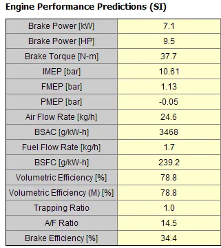
* Results noted at speed = 1800 RPM
1. Air flow rate: It is defined the mass of air that is ingested into the engine cylinder.
`dotm_a` = 24.6 Kg/hr
2. BMEP: Brake mean effective pressure is defined as calculation of engine cylinder pressure that would give the measured brake horsepower. To calculate this we can consider two more mep's, they are IMEP and FMEP.
IMEP: Indicated mean effective pressure it is defined as the average pressure acting on the piston during different cycles.
FMEP: It is defined as the average pressure required to overcome the friction, or in other words the loss of IMEP due to friction.
hence if we deduct FMEP from IMEP the mep what we obtain is BMEP.
therfore BMEP = IMEP - FMEP = 10.61 - 1.13 = 9.48 bar
3. BSFC: Brake specific fuel consumption is defined as the amount of fuel consumed while producing 1 Kw-hr of power. This is driectly obtained in the result from GT-post
BSFC = 239.2 g/Kw-hr
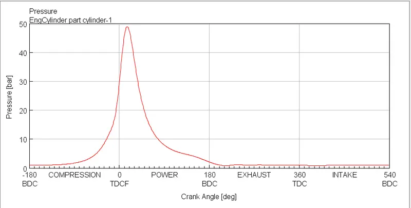
4. In cylinder pressure: It is defined as the pressure inside the cylinder during various strokes of the engine. This can be better represented using a plot. Below is the in-cylinder pressure plot obtained from GT-post.
A snip of the engine performance prediction obtained from GT-post is shown below, this covers all the above disscussed results.
* Next the aim is to increase the power output of the engine by 10% at 3600 rpm, to achieve this one more case is added for 3600 rpm and the simulation is run. Engine performance predictions obtained from GT-post after running the simulation is as shown below,
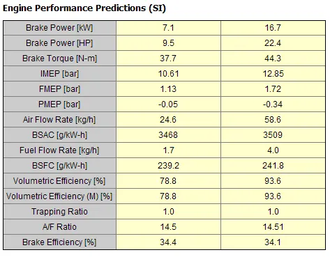
* Comparing the engine power at 1800 rpm and 3600 rpm it is clear that at 3600 rpm the power is more, now we have to increase the power at 3600 rpm by 10% i.e we have a power output = 16.7 kW we need to increase the power = 18.37 kW.
To achieve this let us take into account the power calculation formual, P = BMEP*`A_p`*`barS_P`/4
where `A_p`is crown surface area of piston (m^2), `A_p = pi/4*B^2`
`B` - Bore (m)
`barS_p` is mean piston speed given as, `barS_p = 2*L*N`
L - Stroke length (m)
`N` - Engine speed (rpm)
BMEP - Brake mean effective pressure (bar)
We know that we need a power output of 18.37 kW,
at 3600 rpm we have BMEP = 12.85-1.72 = 11.13 bar
bore, B = 86 mm
hence `A_p = pi/4*(86*10^-3)^2 = 0.0058` m^2
Speed N = 3600 rpm, Using the above data stroke length is calculated
Stroke length, L = 18.37*10^3*60*4/0.0058*2*3600 = 0.09468 m = 94.68 mm
So to obtain 10% increase in power the stroke length of engine is changed to 94.68 mm and simulations is run.
Snip of engine performance prediction from GT-post is shown below,
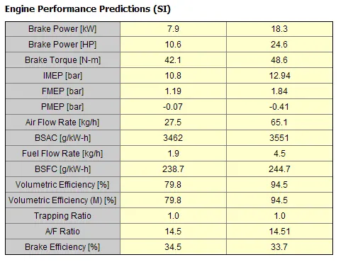
The output power at 3600 rpm is 18.3 kW and hence there is 10% increase in the power output obtained by increase the stroke length to 94.68 mm from 86.07 mm.
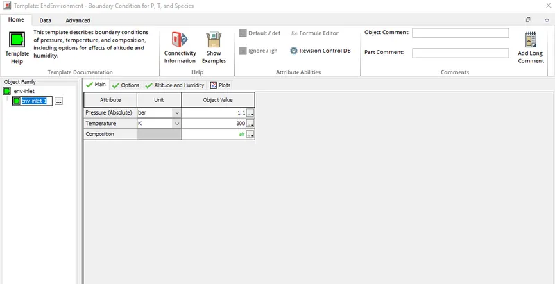
* Another approach is to increase the intake air pressure to increase the power o/p. In the above simulation the intake air pressure is set at 1 bar which gives a power o/p of 16.7 kW at 3600 rpm, intake air pressure is increase to 1.1 bar and the simulations are run. Below is the snip of the pressure increment provided,
Result obtained as follows,
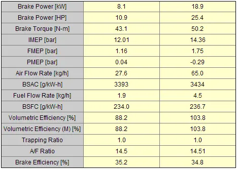
It is observed that at engine speed = 3600 rpm the power o/p from the engine is 18.9 kW which is a 10 % increment, but increasing the intake air pressure comes with the cost of a turbocharger.