Week 2 Air standard Cycle
Based on the concepts you have learnt during the forward kinematics routine, go ahead and write code that can solve an otto cycle and make plots for it.
Here are the requirements
1. Your code should create a PV diagram
2. You should output the thermal efficiency of the engine.
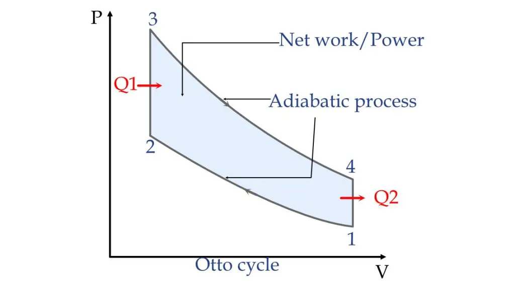
The Otto cycle is an ideal thermodynamic cycle that requires 4-strokes with a piston: Intake, Compression, Ignition, and Exhaust. The fuel and air mixture is compressed, an electric spark ignites it, the sudden expansion pushes the piston producing a power stroke, and the spring action of the piston pushed the combusted gas away.
Process 1 to 2: During this phase the piston will be drawn up, so it can compress the fuel-air mixture that entered the chamber. The compression causes the mixture to increase slightly in pressure and temperature—however, no heat is exchanged. In terms of thermodynamics, this is referred to as an adiabatic process. When the cycle reaches point 2, that is when the fuel is met by the spark plug to be ignited.
Process 2 to 3: This is where combustion occurs due to the ignition of fuel by the spark plug. The combustion of the gas is complete at point 3, which results in a highly pressurized chamber that has a lot of heat (thermal energy). In terms of thermodynamics, this is referred to as an isochoric process.
Process 3 to 4: The thermal energy in the chamber as a result of combustion is used to do work on the piston—which pushes the piston down—increasing the volume of the chamber. This is also known as the power stoke because it is when the thermal energy is turned into motion to power the machine or vehicle.
Process 4 to 1: All waste heat is expelled from the engine chamber. As the heat leaves the gas, the molecules lose kinetic energy causing the decrease in pressure.Then the exhaust phase occurs when the remaining mixture in the chamber is compressed by the piston to be "exhausted" out, without changing the pressure.
1. Swept_Volume(V_s)
The volume swept by the piston during one stroke of the engine is given by:
V_s = pi/4 * d2 * L
2. Clearance Volume (V_c)
The clearance volume is the volume remaining in the cylinder when the piston is at Top Dead Center (TDC). It can be expressed in terms of the swept volume and the compression ratio:
V_c = V_s/(r-1)
r = V1/V2 = (V_s + V_c)/V_c
3. Volume at Stage 1 (BDC) (V1)
At Bottom Dead Center (BDC), the total cylinder volume is the sum of the swept volume and the clearance volume:
V1 = V4 = (V_s + V_c)
4. Volume at Stage 2 (TDC)
At Top Dead Center (TDC), the volume is equal to the clearance volume:
V2 = V3 = V_c
5. Pressure-Volume Relationship
For the isentropic processes (compression and expansion), the relationship between pressure and volume is governed by:
P1 * V1gamma = P2 * V2gamma
gamma = C_p/C_v
6. Ideal Gas Equation of State
The ideal gas law relates pressure, volume, and temperature during the cycle:
(P1 * V1)/T1 = (P2 * V2)/T2
7. Instantaneous Volume (Vtheta)
The volume at any crank angle (theta) can be calculated using the geometry of the crank-slider mechanism:
V(theta) = V_c *[(1 + (r-1)/2) * (1 + R - cos(theta) - (R2 - sin2(theta)).
R = 2 * (Lcr/L)
Thermal Efficiency :
n = 1 - (1/rgamma - 1)
Where,
d is the bore diameter
L is the stroke
Lcr is the connecting rod length
r is the compression ratio
gamma is the specific heat ratio
Theta is the crank angle.
Program Code for the OTTO CYCLE using Python language
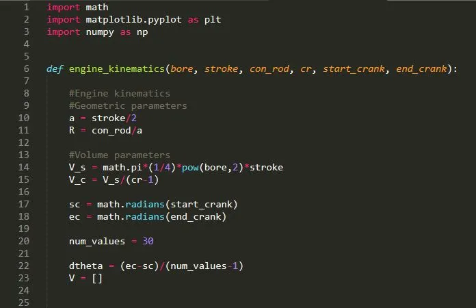
Step1 : Importing the math libraries/tools as matplotlib with numpy.
step 2 : Defining the engine_kinematics such as bore, stroke, connecting rod, compression ratio and crank start-end angles.
step3 : Defining the inputs for stroke and connecting rod and from those values swept volume and clearance volume is calculated.
Crank angles are defined for both start and ending with math function.
An empty value is created for the volume approx 30 num_values is been taken.
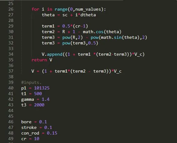
step 4 : Through three terms the volume is been calculated and is stored via append function, where V is the instantaneous volume
V(theta) = V_c *[(1 + (r-1)/2) * (1 + R - cos(theta) - (R2 - sin2(theta)).
step 5 : Inputs have been given for the presuure p1 and temperature t1 with gamma and t3 Temperature
The values of bore, stroke, connecting rod and compression ratio is considered.
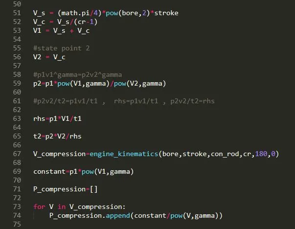
step 6 : Already swept volume and clearance volume is calculated so the volume at stage 1 is calculated by addition of both V_s and V_c as the piston will be at BDC.
step 7 : At stage 2 the volume will be equal to the volume of clearance volume as the piston remains at the TDC and also p2 pressure is calculated using "p1v1gamma=p2v2gamma" .
step 8 : Compression will be calculated in compression stage by utilizing the engine_kinematics functions. The value of Compression is been stored via append .
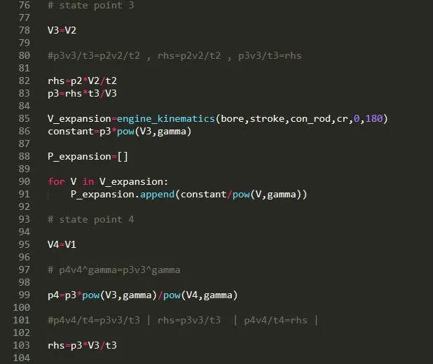
step 9 : At stage point 3 , V3 volume is similar to the V2 and also the pressure because of the piston movement from TDC to BDC at Expansion stage is calculated and its again stored in append function.
step 10 : At stage 4, the volume and pressure is been calculated using p4v4gamma=p3v3gamma
through an additional rhs variable temperature is calculated.
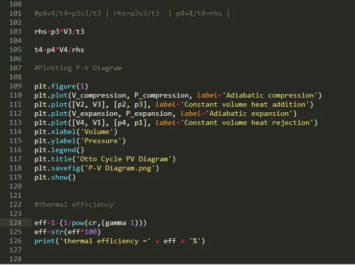
step 11 : Plotting PV Diagram for all the stages such as compression and expansion and is labelled as with their stage processes.
step 12 : for thermal efficiency of the otto cycle, eff=1-(1/pow(cr,(gamma-1))) is implemented and is been displayed in the command box.
P-V Diagram of OTTO CYCLE
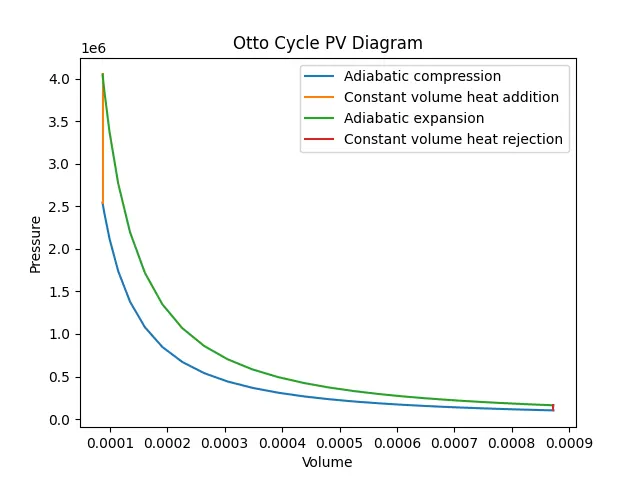
The P-V diagram provides an intuitive and detailed insight into the Otto cycle's thermodynamic behavior. It demonstrates the sequence of processes—compression, combustion, expansion, and heat rejection—allowing to evaluate engine performance and design considerations. The enclosed area highlights the cycle's work output, while the steepness of the compression and expansion curves emphasizes the role of adiabatic processes.
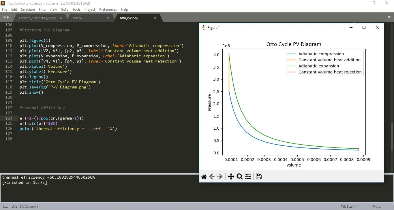
The thermal efficiency (n) of the Otto cycle is a measure of how effectively the engine converts heat energy into useful work. It is influenced primarily by the compression ratio (r) of the engine and the specific heat ratio (gamma) of the working fluid.
The computed thermal efficiency (approximately 60%) reflects the engine's efficiency in converting heat energy into useful work during the cycle. This efficiency is quantified as the ratio between the area enclosed by the expansion and compression curves and the area beneath the constant volume heat addition.
References
https://testbook.com/mechanical-engineering/otto-cycle-process-diagram
https://energyeducation.ca/encyclopedia/Otto_cycle