Air standard Cycle
Week 2 Air standard Cycle
“AIR STANDARD CYCLE PROGRAM USING PYTHON.”
- Objective:-
To write code in Matlab and Python that can solve an otto cycle and Plot PV Diagram.
- The code should create a PV diagram.
- Finding the thermal efficiency of the engine.
- Basic:-
2.1 Ideal Otto Cycle:-
Air standard Otto cycle is used for the SI Engines (Spark Ignition Engine). The cycle Contains Mainly four Processes. In the overall cycle, suction and Exhaust are neglected,
also power consumption is not considered.
The Ideal Otto cycle consists of the four processes which are as below
When the piston in the cylinder of the Internal Combustion Engine (SI Engine) moves from BDC (i.e Bottom Dead Centre) to TDC (i.e Top Dead Centre) the Pressure and volume Relatively change, which is represented on the Diagram known as PV-Diagram.
The ideal PV-Diagram can be seen below
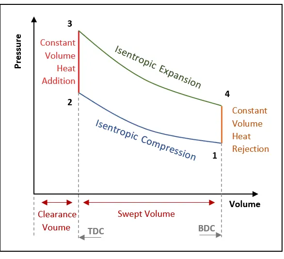
The terms related to the otto cycle is as discussed below.
2.2 Terms in the Otto cycle:
Compression ratio (cr) = Volume before compression/volume after compression also, Compression ratio (cr) = `(Vs+Vc)/(Vc)`
Where:-
V1= volume before compression = V_swept + V_clearance
V2 = volume after compression = V_clearance
Vs = V_swept , Vc = V_clearance
Therefore, Compression ratio (cr) = `(V1)/(V2)`
- Expansion ratio (er):- It is the ratio of volume after Expansion to the volume before compression.
Similarly, as the compression ratio, we can get an Expansion ratio.
Therefore, Expansion ratio (er) = `(V4)/(V3)`
Note:- for Otto cycle compression Ratio = Expansion ratio i.e (cr=er).
iii. Swept volume and Clearance volume:- Swept Volume (V_s) is a volume Before compression stroke. Also known as stoke volume and Displacement volume. Similarly, Clearance volume (V_c) is a volume after compression stroke.
The Behavior of the piston and crank cause changes in the process of the Otto cycle PV diagram is as shown below.
Explanation for Python:
Step-1: Importing Libraries.
Before Going to Do program we are using import command as follows.
Step-2: Basic Program.
First, we are going to do the basic program with the help of defined state variable points.
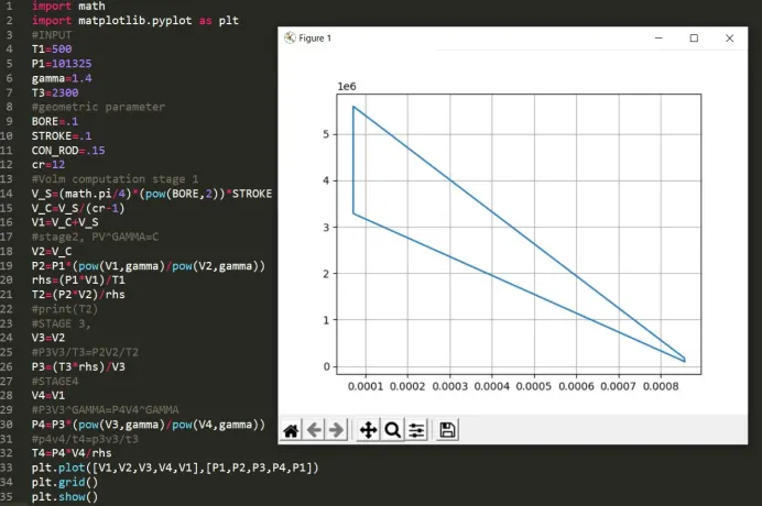
import math
import matplotlib.pyplot as plt
#INPUT
T1=500
P1=101325
gamma=1.4
T3=2300
#geometric parameter
BORE=.1
STROKE=.1
CON_ROD=.15
cr=12
#Volm computation stage 1
V_S=(math.pi/4)*(pow(BORE,2))*STROKE
V_C=V_S/(cr-1)
V1=V_C+V_S
#stage2, PV^GAMMA=C
V2=V_C
P2=P1*(pow(V1,gamma)/pow(V2,gamma))
rhs=(P1*V1)/T1
T2=(P2*V2)/rhs
#print(T2)
#STAGE 3,
V3=V2
#P3V3/T3=P2V2/T2
P3=(T3*rhs)/V3
#STAGE4
V4=V1
#P3V3^GAMMA=P4V4^GAMMA
P4=P3*(pow(V3,gamma)/pow(V4,gamma))
#p4v4/t4=p3v3/t3
T4=P4*V4/rhs
plt.plot([V1,V2,V3,V4,V1],[P1,P2,P3,P4,P1])
plt.grid()
plt.show()
- Thermodynamic relation during compression and Expansion.
- Piston kinematics to determine How the volume change from TDC to BDC and how
combustion volume changes as a function of the crank angle.
Here, we are taking all the parameters the same as discussed in step 1 and 2, but we need a different formula for the calculation of the volume change inside the combustion
chamber. The required relationship we can get by the following formula. The Formula for the Engine kinematics is as follows.
`V/(Vc) = 1+ 0.5(cr-1)* [ R+1 -cos(theta) — (R² -sin²(theta))⁰.5]`
To use this formula in the program we simplified it. Hence, To simplify the formula we
divided formula into three sub formulas (terms) as follows.
`term1 = 0.5*(cr-1)`;
`term2= R+1-cos(theta)`;
`term3=(R²-sin²(theta))⁰.5`;
At last, After combining the terms to get the final formula
`V=(1+term1*(term2-term3))*V_c`
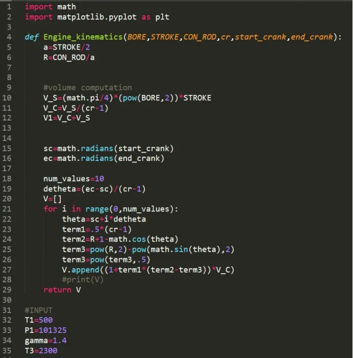
After that our Engine kinematics formula is used as a function in the program is as
shown below.
def engine_kinematics(bore,stroke,con_rod,cr,start_crank,end_crank):
# Geometric Parameters
a = stroke/2
R = con_rod/a
dtheta = (ec-sc)/(num_values-1)
V = []
for i in range(0,num_values):
theta = sc + i*dtheta
term1 = 0.5*(cr-1)
term2 = R + 1 - math.cos(theta)
term3 = pow(R,2) - pow(math.sin(theta),2)
term3 = pow(term3,0.5)
V.append((1+ term1 * (term2 - term3))*V_c)
return V
Where:-
We need the formula of engine kinematics to create the volume Arrays concerning the compression and Expansion Processes. After that, we can use it in our Otto cycle Program. Also, we need to calculate the pressure that corresponds to the volume.
Therefore, We defined the Engine kinematics as the function.
Since we have a function so we need not pre-define the value of the parameters related to it such as values of bore, stroke, connecting rod length, etc.
iii. Now defining the sc and ec (i.e starting crank angle and ending crank angle). Because we want to get several values between the starting crank and ending crank position and each of those values we need to get the volume. hence using ec and sc and assigning it to
the dtheta which is known as a crank angle spacing. Also defined the number of values is equal to 10 as follows.
“# Position of Starting Crank and Ending Crank
sc = math.radians(start_crank)
ec = math.radians(end_crank)
loop executed each time the value calculated in the for-loop gets store in the empty array.
- But to generate the multiple values we need one more command called as append.”.append” is used to continuously append (increase) the value and store it in the empty array, using “return V” to get multiple output values of volume.
Step-4: Defining the Compression and Expansion processes.
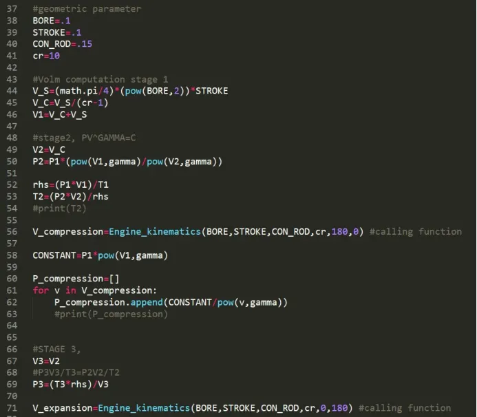
To define the compression and Expansion processes in the program we took help to the engine kinematic function as shown below.
# for Compression process at State point 2
V_comp = engine_kinematics(bore,stroke,con_rod,cr,180,0)
const = p1*pow(v1,gamma)
P_comp =[]
for v in V_comp:
P_comp.append(const/pow(v,gamma))
# for Expansion process at State point 4
V_exp = engine_kinematics(bore,stroke,con_rod,cr,0,180)
const = p3*pow(v3,gamma)
P_exp =[]
for v in V_exp:
P_exp.append(const/pow(v,gamma))
taken starting crank angle is at 0 degrees and the ending crank angle is 180 degrees (i.e piston moves from TDC to BDC).
Note:- Here We took the crank angle for reference to the compression and expansion process not a movement of the piston. Also, Suction and exhaust are neglected.
Step-5: Calculating Thermal Efficiency.
we are using the efficiency formula for the ideal otto cycle in percentage we can determine the efficiency of the otto cycle. The Thermal efficiency formula in percentage is as following.,
Percentage_Efficiency = `1–1/(cr^(gamma-1))*100`
# Calculating Thermal Efficiency
n = pow(pow(cr,(gamma-1)),-1)
Percentage_Efficiency = (1-n)*100
print(Percentage_Efficiency)
Step-6: Creating Plot.
After defining all the terms we need the output so to do that we are using the plot command and plotted all the processes.
After properly arranging the program we get out the desired program and output which is shown below.
Final Program in Python:
import math
import matplotlib.pyplot as plt

def Engine_kinematics(BORE,STROKE,CON_ROD,cr,start_crank,end_crank):
	a=STROKE/2
	R=CON_ROD/a


	#volume computation
	V_S=(math.pi/4)*(pow(BORE,2))*STROKE
	V_C=V_S/(cr-1)
	V1=V_C+V_S


	sc=math.radians(start_crank)
	ec=math.radians(end_crank)

	num_values=10
	detheta=(ec-sc)/(cr-1)
	V=[]
	for i in range(0,num_values):
		theta=sc+i*detheta
		term1=.5*(cr-1)
		term2=R+1-math.cos(theta)
		term3=pow(R,2)-pow(math.sin(theta),2)
		term3=pow(term3,.5)
		V.append((1+term1*(term2-term3))*V_C)
		#print(V)
	return V

#INPUT
T1=500
P1=101325
gamma=1.4
T3=2300

#geometric parameter
BORE=.1
STROKE=.1
CON_ROD=.15
cr=10

#Volm computation stage 1
V_S=(math.pi/4)*(pow(BORE,2))*STROKE
V_C=V_S/(cr-1)
V1=V_C+V_S

#stage2, PV^GAMMA=C
V2=V_C
P2=P1*(pow(V1,gamma)/pow(V2,gamma))

rhs=(P1*V1)/T1
T2=(P2*V2)/rhs
#print(T2)

V_compression=Engine_kinematics(BORE,STROKE,CON_ROD,cr,180,0) #calling function

CONSTANT=P1*pow(V1,gamma)

P_compression=[]
for v in V_compression:
	P_compression.append(CONSTANT/pow(v,gamma))
	#print(P_compression)


#STAGE 3,
V3=V2
#P3V3/T3=P2V2/T2
P3=(T3*rhs)/V3

V_expansion=Engine_kinematics(BORE,STROKE,CON_ROD,cr,0,180) #calling function

CONSTANT=P3*pow(V3,gamma)

P_expansion=[]
for v in V_expansion:
	P_expansion.append(CONSTANT/pow(v,gamma))
	#print(P_compression)
#STAGE4
V4=V1
#P3V3^GAMMA=P4V4^GAMMA
P4=P3*(pow(V3,gamma)/pow(V4,gamma))
#p4v4/t4=p3v3/t3
T4=P4*V4/rhs

def cal_eff(cr,gamma):
    EFFF=1-(1/pow(cr,gamma-1))
    return EFFF

s=cal_eff(12,1.4)
print('thermal efficiency= ',s)
#print(T4)
#V=Engine_kinematics(BORE,STROKE,CON_ROD,cr,start_crank,end_crank) #calling function
#print(V)
plt.plot([V2,V3],[P2,P3],label='Heat Addition')
plt.plot(V_compression,P_compression,label='Isentropic Compression')
plt.plot(V_expansion,P_expansion,label='Isentropic Expansion')
plt.plot([V4,V1],[P4,P1],label='Heat Rejection')
plt.xlabel('Volume',fontsize=14)
plt.ylabel('Pressure',fontsize=14)
plt.title('Otto cycle',fontsize=20)
plt.legend()
plt.grid()
plt.show()
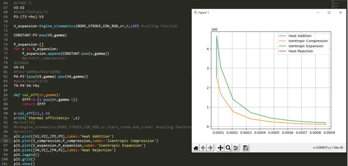
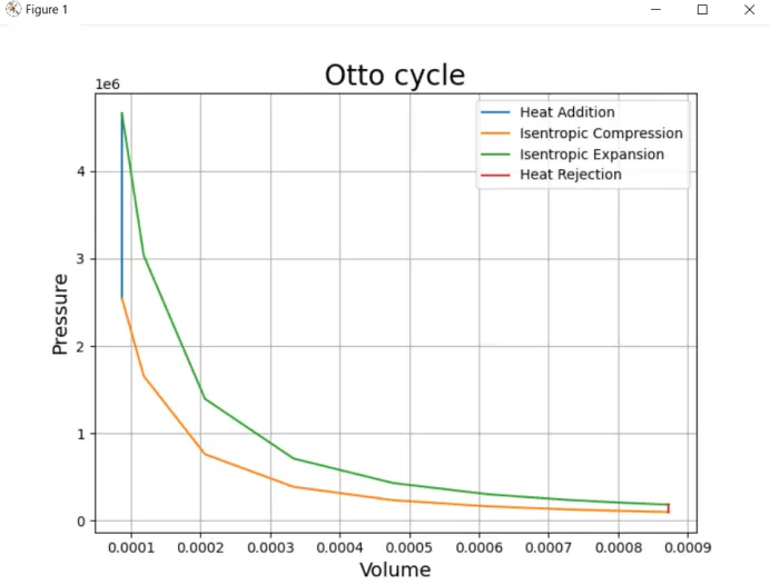
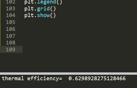
By Executing the Program we get our required output as,
- Otto cycle plot of PV diagram and
- Thermal efficiency in percentage.
The Output is as follows.
Reference:-
https://en.wikipedia.org/wiki/Otto_cycle