Week -2
1.
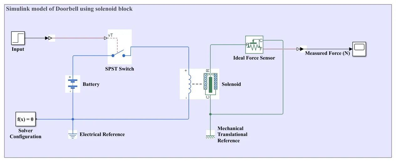
1. Input – Represents the control signal or power source (likely the Battery).
2. SPST Switch – A Single-Pole Single-Throw switch to turn the circuit on/off.
3. Battery – Provides electrical power to the system.
4. f(x) = 0 – Likely a ground or reference point in the model.
5. Solver Configuration – Sets simulation parameters (e.g., time step, solver type).
6. Electrical Reference – Ground (0V reference) for the electrical circuit.
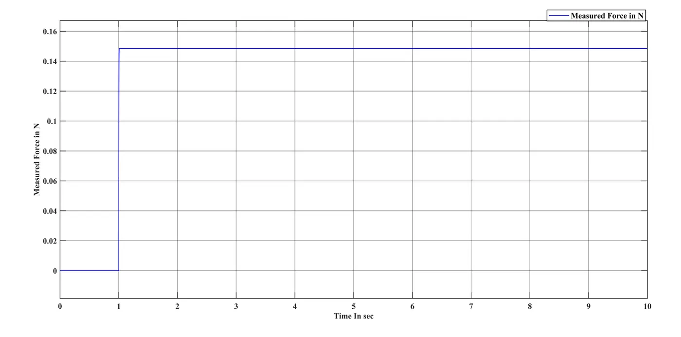
7. Ideal Force Sensor – Measures the force generated by the solenoid.
8. Solenoid – Converts electrical energy into mechanical force (outputs linear motion).
9. Mechanical Translational Reference – Ground reference for mechanical motion.
Model:
Output:
2.
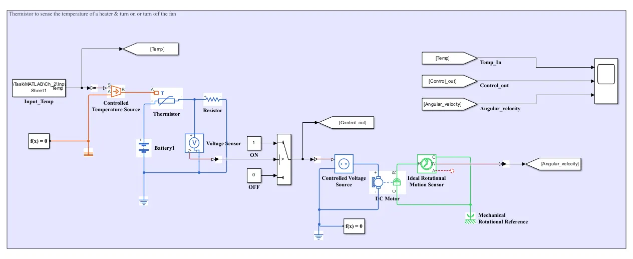
This system controls temperature using a thermistor (NTC type, 50Ω at 27°C) to monitor a heater's temperature, which follows a predefined profile (20°C→27°C→23°C). The thermistor's resistance changes with temperature and forms a voltage divider with a fixed 50Ω resistor, producing a measurable voltage. A comparator checks this voltage against a 25°C threshold - triggering a fan (1500 units speed) when the temperature exceeds 25°C and turning it off when below. The fan's ON/OFF state is determined by the comparator's output, completing this closed-loop temperature regulation system.
Model:
Input:
| Time | Temp in Deg.C |
| 0 | 20 |
| 5 | 20 |
| 9 | 20 |
| 10 | 27 |
| 15 | 27 |
| 30 | 27 |
| 30 | 23 |
| 35 | 23 |
| 40 | 23 |
| 50 | 23 |
Output:
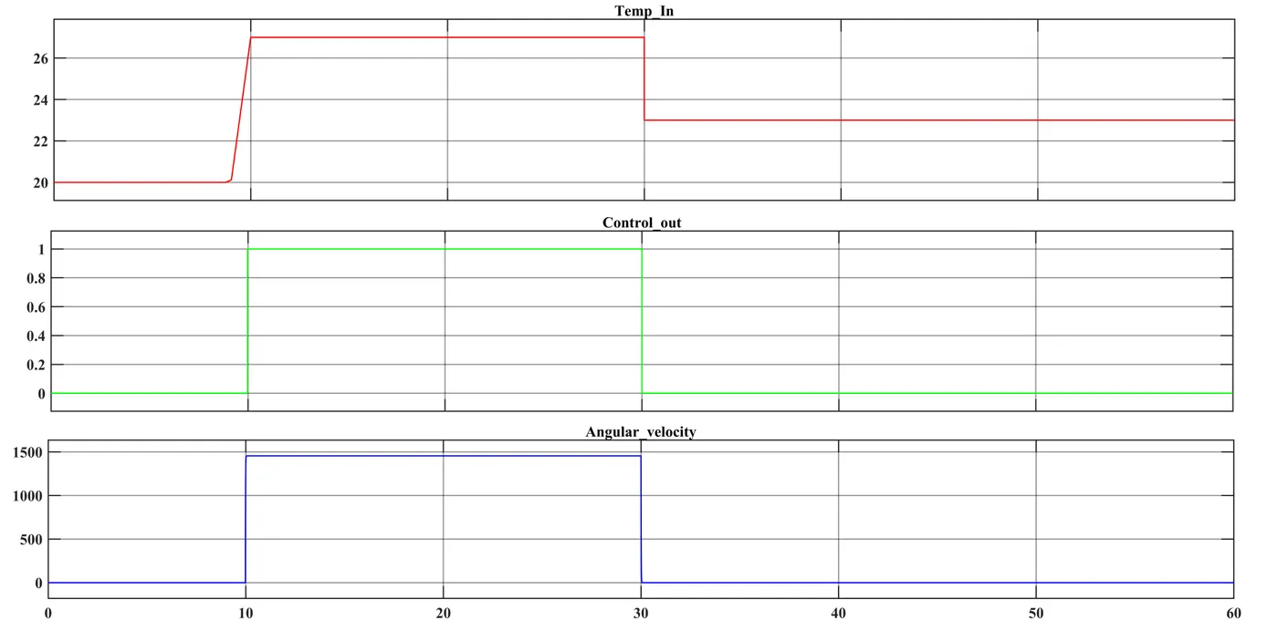
The above three graph represents Input temperature, control output, Angular Velocity.
- Input Temperature
- Shows the heater's temperature changing over time (20°C → 27°C → 23°C).
- Helps track when the temperature crosses the 25°C threshold.
- Control Output
- Turns ON (1) when temperature > 25°C, OFF (0) when ≤ 25°C.
- Acts as the switch signal for the fan.
- Angular Velocity
- Fan spins fast (~1500) when ON, stops (0) when OFF.
- Matches the control signal, proving the system works.