Week -2
OBJECTIVE:
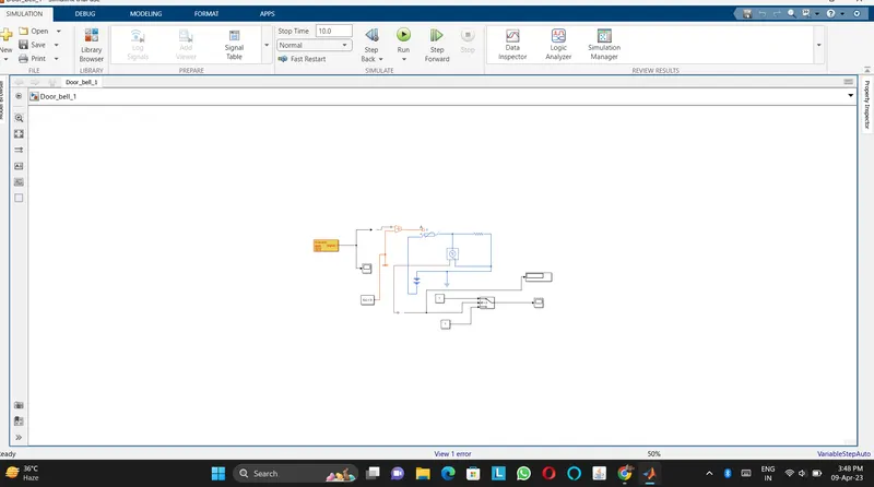
- Make a Simulink model of Doorbell using solenoid block with the following details:
In the above arrangement, when the switch is closed the electromagnet receives electrical power from the battery and pulls the metal arm to hit the bell producing sound.
Create a situation where the switch is closed for 2 seconds and then released. Observe the physical movement of the plunger.
Assume remaining parameters.
2. Use a thermistor to sense the temperature of a heater & turn on or turn off the fan as per the below conditions:
Temperature source: 20 °C from 0 to 10 seconds, 27 °C from 10 to 30 seconds, 23 °C from 30 to 50 seconds
Fan conditions: ON if the temperature above 25 °C, OFF otherwise
Q.1.
Ans:
Introduction
The electric doorbell is a simple circuit that triggers a sound on the completion of the circuit by pressing the button. It is this simplicity that makes the doorbell such a marvel. The simple devices in the doorbell but the scientific principle of electromagnetism into action in a useful way. In order to understand the operations of an electric bell, you first need to understand what is an electromagnet. Well, to put it in simple words, an electromagnet is basically a type of magnet in which the magnetic field is produced with the help of an electric current. When electrical current flows through an electromagnet it works as a standard magnet (generating magnetic fields). When the power generation to an electromagnet stops, the production of the magnetic field also stops.
So, in an electric bell, an electromagnet forms an important part along with Armature, Spring, Armature rod, Hammer and a Gong.
The image below shows the internal mechanism of an electric bell.
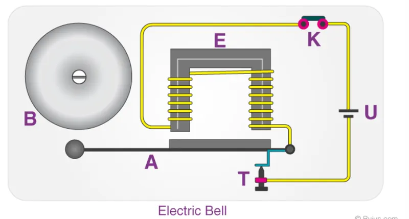
An electric source, for example, a battery can be used to power the electromagnet used in an electric bell. The electric circuit is completed by installing a push switch which you can press to generate sound in an electric bell. The switch also acts as the circuit breaker.
So once the setup is completed, when the switch is pressed, the circuit loop is complete which causes the current to flow through the circuit. The arm which strikes the gong is connected to a spring at one end and an iron ball at the other end. This is called a hammer or a striker. The arm is attached to an iron strip which is attracted to the electromagnet when the circuit is complete and the current flows.
Why does this happen? It’s mainly because the magnetic field created by the electromagnet attracts the iron strip towards it when the circuit is complete. This is the moment when you hear the ringing sound since the hammer keeps hitting the gong. Meanwhile, at its rest position, the hammer is held away from the gong on account of the spring attached to its arm. This is an anchored arm.
Process of the working of an electric bell
Now that you have an understanding of the important parts in an electric bell, the step-by-step process of the working of the electric bell is described below:
- The switch is pressed and current flows through the circuit.
- The electromagnet is powered and generates a magnetic field that attracts the iron strip towards it.
- The striker strikes the gong (bell).
- When the striking arm strikes the gong, the contact is broken and the current stops flowing through the circuit.
- This causes the electromagnet to lose its magnetic field.
- The connected spring arm returns the striker to its original rest position.
- The contact is restored and current flows through the circuit (provided the main switch is still pressed).
- The process is repeated from the beginning.
Practically using for door bell in matlab tool
PS-Simulink and Simulink-PS converter, Scopes, Displays, Pulse generator, electrical and mechanical references, solenoid, Battery, switch, ideal Transalation motion sensor, solver configuration. These are the following simscape and Simulink blocks that are going to use in this simulation.
Q.2.
OBJECTIVE:
Create a simulink model of thermistor to sense the temperature of a heater & turn on or turn off the fan.
Conditions:
Temperature source: 20 °C from 0 to 10 seconds, 27 °C from 10 to 30 seconds, 23 °C from 30 to 50 seconds.
Fan conditions: ON if the temperature above 25 °C, OFF otherwise.
Blocks used in model:
- Repeating Sequence Stair
- Controlled Temperature Source
- Thermistor
- Resistor
- Voltage sensor
- Battery
- Switch
- Lamp
- Scope
- Dsiplay
- PS-Simulink Converter
- Simulink-PS Converter
- Solver Configuration
Thermistor: thermal resistor is defined as a type of resistor whose electrical resistance varies with changes in temperature. Although all resistor's resistance will fluctuate slightly with temperature, a thermistor is particularly sensitive to temperature changes.
Thermistors act as a passive component in a circuit. They are an accurate, cheap, and robust way to measure temperature. While thermistors do not work well in extremely hot or cold temperatures, they are the sensor of choice for many different applications. Following is the Simulink block assembly for Thermistor based heater. And with condition follows here as :
1. 0-10 sec temperature 293
2. 10-30 secs temperature 300
3. 30-50 secs temperature 296
and you can see these details in plot basis in signal builder block where the input is inserted with these signals.