Week -2
Report on Second Challenge:
- 1. Make a Simulink model of Doorbell using solenoid block with the following details:
In the above arrangement, when the switch is closed the electromagnet receives electrical power from the battery and pulls the metal arm to hit the bell producing sound.
Create a situation where the switch is closed for 2 seconds and then released. Observe the physical movement of the plunger.
Ans:
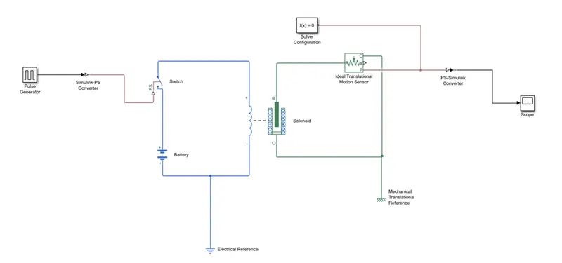
Below is the Description of all the blocks used in this model:
Model Working: When Switch is closed the electromagnet receives electrical power from battery and pulls arm then ideal translational motion sensor sense the movement and gives output by scope.
- I) Solenoid: Electrical signal converts into kinetic energy. The solenoid block represents the electrical characteristics and generated force. It is connected with switch and battery and we get a complete electrical circuit. The port c is connected with mechanical reference.
- II) Battery: Gives supply to solenoid.
III) Switch: To complete the connection when it close supply flows through circuit and pulls metal arm to hit. It is used to control the external physical signal. If the external signal is greater than the threshold parameter then the switch is closed, otherwise switch is open.
The positive terminal of the switch is connected to switch and the negative terminal is connected to the electrical reference.
- IV) Pulse Generator: Pulse generator block generates square wave pulses at regular interval pulse generated from PG is converted to Simulink to physical signal and given to perform switch function. It is used to create square wave pulses at regular intervals. The block waveform parameters Amplitude, pulse width, period and phase delay, determine the shape of the output waveform.
Values of PG: Amplitude- 1, pulse width - 20, period - 10 sec. phase delay - 2
- V) Ideal Translational motion sensor: This motion sensor senses Physical movements of solenoid. It is connected with solenoid block R to observe the movement of the plunger.
- VI) Scope: Scope is connected with the ideal translational sensor to get the output.
VII) PS-Simulink converter: It is used to convert the physical signal to Simulink signal.
VIII) Solver Configuration: Each physical network represented by a connected sim scape blocks requires solver setting information for simulation
Output:
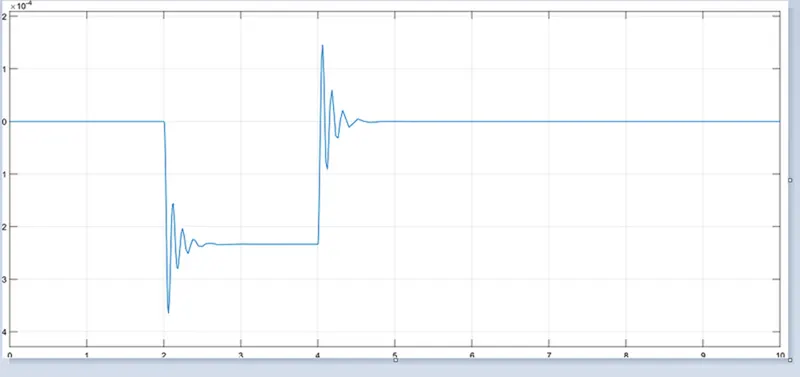
Observations: From 0 to 2sec. output is null and from 2 to 4 sec. it gives oscillations.
- 2. Use a thermistor to sense the temperature of a heater & turn on or off the fan as per below conditions:
Temperature sources 20-degree C from 0 to 10 sec., 27-degree C from 30 to 50 sec.
Fan Condition: ON if the temperature above 25-degree C, OFF otherwise.
Ans:
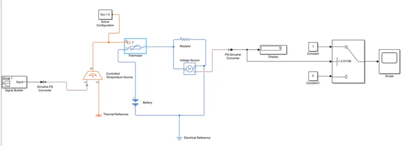
Following are the block details with description:
- I) Thermistor: Temperature sensing element. Negative temperature coefficient thermistor using B-parameter equation. Thermistor is a type resistor whose resistance is based upon temperature.
- II) Controlled Temperature Source: The block represents an ideal energy source in a thermal network that can maintain controlled temperature difference regardless of the heat flow rate. It represents an ideal source of thermal energy, that can maintain a controlled temperature difference regardless of the heat flow rate. The temperature difference is set by the physical signal port S. A positive temperature difference causes the temperature at port B to be greater than the temperature at port A.
III) Signal Builder: Function to create and access signal. It is used to input the values as per given conditions:
At point 1, Time=0 seconds, Temperature=293 K
At point 2, Time=10 seconds, Temperature=293 K
At point 3, Time=10 seconds, Temperature=300 K
At point 4, Time=30 seconds, Temperature=300 K
At point 5, Time=30 seconds, Temperature=296 K
At point 6, Time=50 seconds, Temperature=296 K
- IV) DC voltage source: This block maintains time invariant (constant) voltage across its output terminals independent of the current through the source. Voltage source which represents dc or ac
- V) Voltage Sensor: The block represents ideal voltage sensor, a device that converts voltage measured between any electrical connections into physical signal proportional to the voltage. The voltage sensor is used to convert the voltage measured between two points into a physical signal.
- VI) Switch: Switch block passes the first input or the third input signal based on the value of the second input. The first and third inputs are date input. The second input is a control input. Specify the condition under which the block passes the first input by using the criteria for passing first input and threshold parameters.
VII) Resistor: A linear resistor is used is used in order to control the amount of current from the battery.
VIII) Solver Configuration: Each physical network represented by a connected Sims cape blocks requires solver setting information for simulation.
Model Operation: As per the given conditions created the signals from signal builder block as the model shown above. Firstly, convert all temperature which are in degree Celsius into kelvin by adding 273.15 then connect the constant block instead of signal builder and check the voltage of 25 degree Celsius (25+273.15) in display that value inserted as threshold value in switch then again connect the signal builder and check the output from scope.
Output:
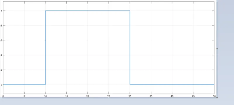
Observations: Output shows that switch is ON when temp.is above 25 which is in interval of 10 to 30 secs.