Week -2
1.Make a Simulink model of Doorbell using solenoid block.
Aim:
To make a Simulink model of a doorbell using a solenoid block as when the switch is closed the electromagnetic receives electrical power from the battery and pulls the metal arm to hit the bell producing sound.
To create a situation where the switch is closed for 2 seconds and then released. Where we have to observe the physical movement of the plunger.
OBJECTIVES OF THE PROJECT:
- To make a Simulink model of a doorbell as mentioned.
- To create a situation where the switch is closed for 2 seconds and observe the physical movement of the plunger.
BODY OF THE CONTENT:
Simulation block diagram:
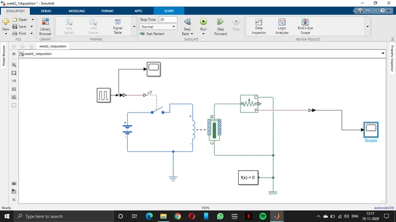
Simulation block diagram explanation:
Here I used 11 types of blocks:
- Pulse Generator
- Simulink-PS Converter
- Battery
- SPST Switch
- Electrical Reference
- Solenoid
- Ideal Translational Motion Sensor
- Solver Configuration
- Mechanical Translational Reference
- PS-Simulink Converter
- Scope
Pulse Generator:
Pule generator is a type of input generator here we use an input as a train pulse with the same period for on and off time.
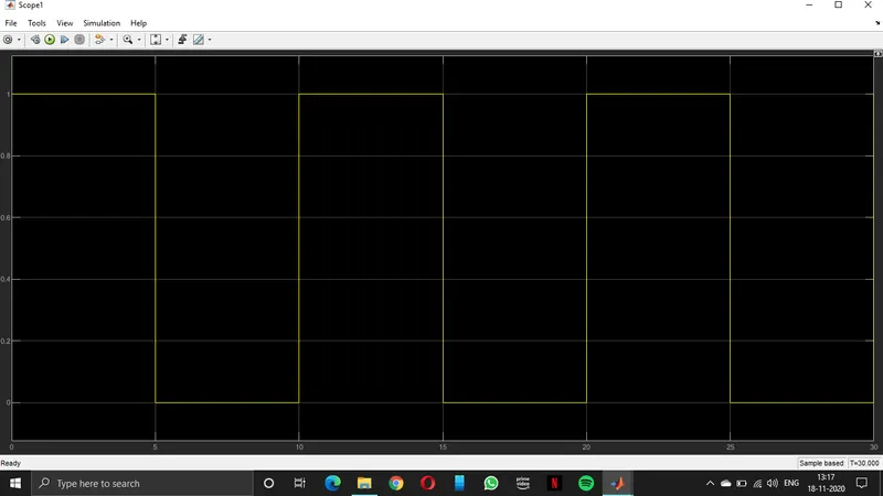
As we see it is the pulse generator output.
Simulink-PS Converter:
Simulink-PS Converter is used to connect Simulink blocks with Simscape blocks.
Battery:
The battery is used to supply power to the required circuit. Generally, batteries get discharged after some time but here in Simulink, we are assuming an infinite source battery for the simulation process.
SPST Switch:
The full form os SPST is single pole single throw.
Here we use this switch to give a connection from the battery to the electric circuit.
Electrical Reference:
The Electrical reference is generally a ground point which must be connected to an electric circuit to avoid faults.
Solenoid:
The solenoid is a block that has both electrical characteristics and mechanical characteristics. When an electrical signal is given it gives the output as mechanical as a force for the solenoid. To remove the effect of the noise of the spring we can decrease the spring constant. To change the direction of output of the solenoid we have to motion direction.
Ideal Translational Motion Sensor:
The ideal translational motion sensor is a sensor which senses the motion of the solenoid output.
Solver Configuration:
The Solver Configuration block is a necessary block for all Simscape models. It is used to initialize and the sample time for the simulation.
Mechanical Translational Reference:
The mechanical Translation reference is a point where it should be connected to mechanical systems. This is the same as an electrical reference but where this is used for mechanical systems.
PS-Simulink Converter:
This is the reverse of the Simulink-PS Converter. This is used to connect Simscape blocks with Simulink blocks.
Scope:
The scope is used to see the output/results.
Results:
Here I have classified the overall results into three categories
- Default type.
- Decreasing spring constant and keeping damping constant.
- Decreasing spring constant and increasing damping.
1.Default type:
In the default type, we can see that the spring constant and damping both constant results.
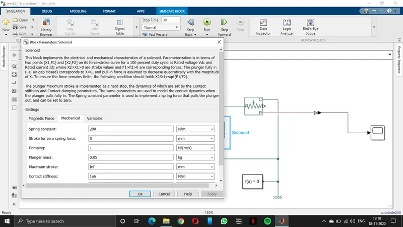
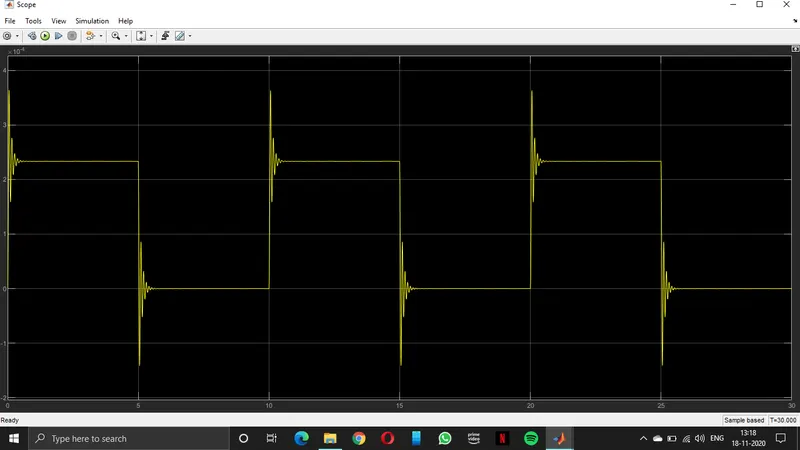
If we observe in the above picture the noise and settling time is more in the output.
2.Decreasing spring constant and keeping damping constant:
In Decreasing spring constant and keeping damping constant.
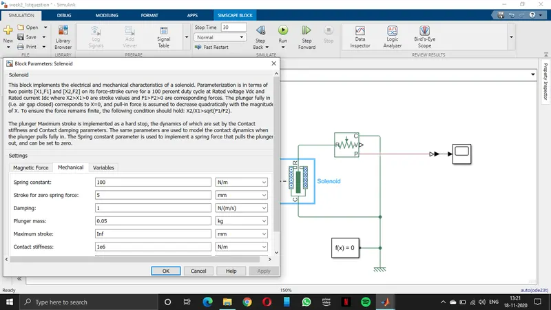
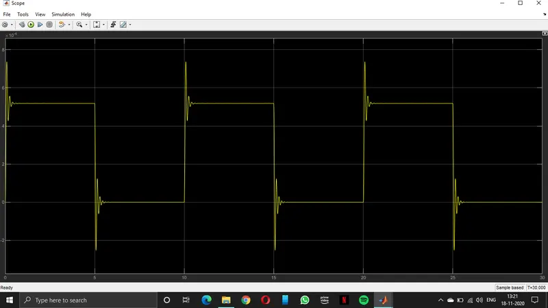
If we observe in the above picture the noise is reduced and settling time is the same due to keeping damping constant.
3.Decreasing spring constant and increasing damping:
In Decreasing spring constant and increasing damping result.
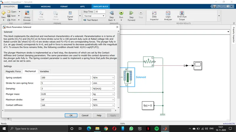
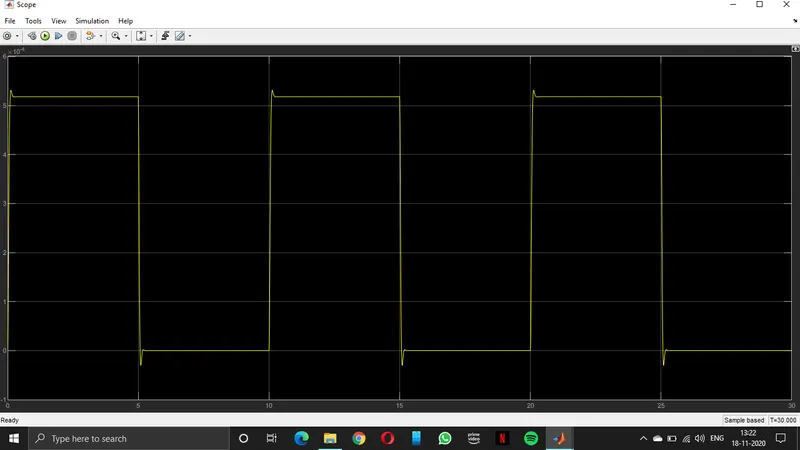
If we observe in the above picture the noise and settling time both are improved and the result is more efficient.
CONCLUSION:
If we observe the results when we decrease the spring constant the noise is reduced and when we increase the damping the settling time is reduced.
2. Use a thermistor to sense the temperature of a heater & turn on or turn off the fan as per given conditions.
Aim:
- To sense the temperature of a heater using a thermistor.
- Turn ON if the temperature above 25 °C, OFF otherwise.
OBJECTIVES OF THE PROJECT:
- To create a signal train with different temperature values.
- To sense the temperature of a heater using a thermistor.
- Turn ON if the temperature above 25 °C, OFF otherwise.
BODY OF THE CONTENT:
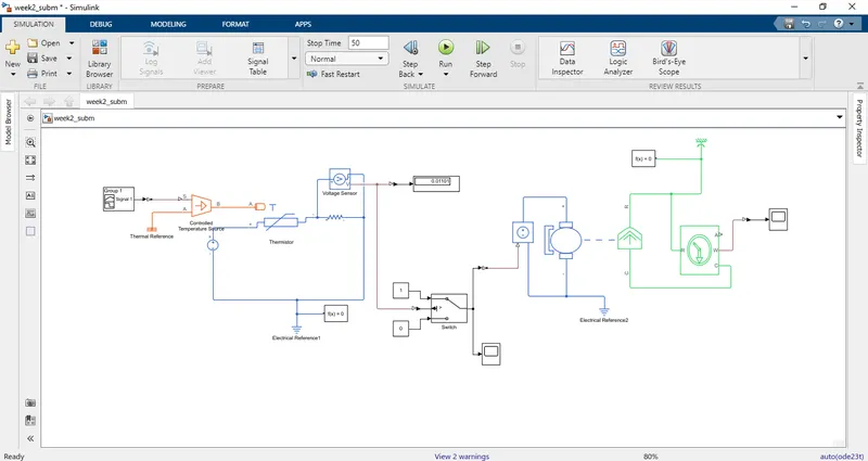
Simulation block diagram:
Simulation block diagram explanation:
Here I used 18 types of blocks:
- Signal builder.
- Thermal reference.
- Simulink - Ps converter.
- Controlled temperature source.
- Thermistor.
- Resistor.
- Voltage Sensor.
- Electrical reference.
- Solver Configuration.
- Simulink - Ps converter.
- Switch.
- Constant to switch.
- Display.
- Scope.
- Controlled Voltage source.
- DC motor.
- Ideal Rotational motion sensor.
- Ps - Simulink converter.
Signal builder:
The signal builder used here is to generate different types for different time intervals. We can adjust it to the required time and required amplitude. Here we use Signal builder to generate different temperatures for different time intervals.
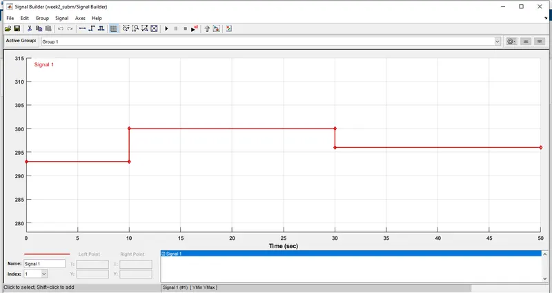
The signals we used here are in kelvin degree so that we cant change all the parameters of the blocks.
Thermal reference:
The Thermal reference is used in the circuit where we use thermal blocks and the reference temperature is zero.
Simulink - Ps converter:
Simulink-PS Converter is used to connect Simulink blocks with Simscape blocks.
Controlled temperature source:
The Controlled temperature source is a source where we give two temperatures where it gives the output as the difference of both the inputs in the Matlab.
Thermistor:
The thermistor is a material when we give electrical supply then the output is a thermal signal.
Resistor:
The resistor is an element when we give an electrical signal it opposes the flow of current. Which is used to sense the voltage drop in the circuit.
Voltage Sensor:
the voltage sensor is used to sense the voltage drop across the resistor. which is used as a threshold voltage for a switch we used here.
Electrical reference:
The Electrical reference is generally a ground point which must be connected to an electric circuit to avoid faults.
Solver Configuration:
The Solver Configuration block is a necessary block for all Simscape models. It is used to initialize and the sample time for the simulation.
Simulink-PS Converter:
Simulink-PS Converter is used to connect Simulink blocks with Simscape blocks.
Switch:
The switch is used here to give a signal to on or off the dc motor which we can use as a fan. Based on the threshold value given to it will act as ON or OFF for the required level.
Constant to the switch:
The constant to the switch is given as on or off there are two where one is a high signal and one is a low signal. When the voltage crosses the threshold value given to the switch then the switch gives the output as high otherwise low.
Display:
The display is used to see the voltage drop across the resistor.
Scope:
The scope is used two times in the overall simulation one to see the output of the switch and another to see the direction of rotation of the dc motor.
Controlled Voltage source:
The controlled voltage source is used to give voltage or start signal to the DC motor. The input to the controlled voltage source is the output of the switch. When the output of the switch is high the controlled voltage gets activated and gives voltage to the DC motor otherwise standstill.
DC motor:
The DC motor is used in the project to be used as a fan. Since we have to use a fan for different conditions given.
Ideal Rotational motion sensor:
The Ideal Rotational motion sensor is used in the project to measure the motion of rotation of the DC motor. By measuring the motion of the motor we can say when the motor is on or off.
PS-Simulink Converter:
This is the reverse of the Simulink-PS Converter. This is used to connect Simscape blocks with Simulink blocks.
Results:
There are two results we have to observe in the project they are:
- The output of the switch.
- The output of the Rotational Motion Sensor.
The output of the switch:
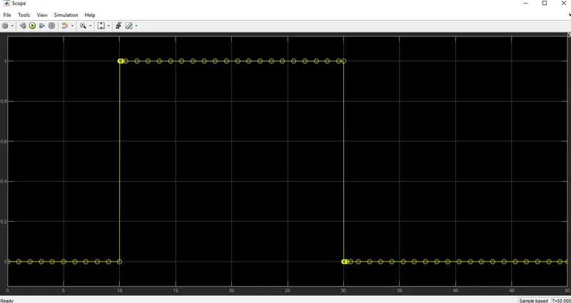
The output of the switch shown below gives us the idea that the switch gives high output in the time period 10 to 30seconds
remaining all the time the output is low.
That shows that in that particular period the input to the switch is more than the threshold value inserted.
The output of the Rotational Motion Sensor:
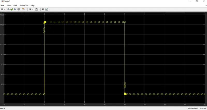
The output of the rotational motion sensor shows that when the motor is rotating and when the motor is not rotating.
when the motor rotates then the output is more than 1400. That means the speed or angular rotation of the motor.
The below figure shows the actual output of the rotational motion sensor.