Week -2
- Make a Simulink model of Doorbell using solenoid block with the following details:
In the above arrangement, when the switch is closed the electromagnet receives electrical power from the battery and pulls the metal arm to hit the bell producing sound.
Create a situation where the switch is closed for 2 seconds and then released. Observe the physical movement of the plunger
ans-
:- Circuit Diagram of Door Bell.
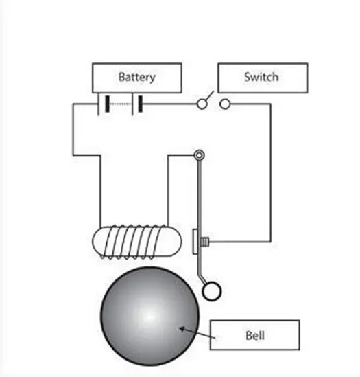
The theory of this door bell is, there is a solenoid or we can say electromagnet which is with wire winding and a small metal piston inside it.The piston is connected with spring also, which help it to be in it's postion and also to regain it's position if displacement of piston happen. When electric current flows through the wire, the electromagnetic field is generated which pulls the metal piston towards itself and as piston hits the bell the circuit break and spring pull the piston away from bell. This process continues till switch is ON.
Simulink Model
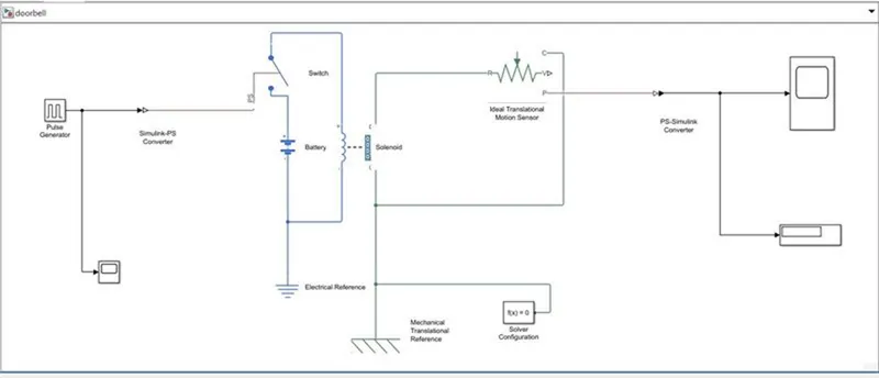
Simulink Model
In this model, we use Pulse Generator for input signal and by using simulink-ps convetor we convert input signal to physical signal. The Switch is used for completeing the circuit, battery for power sourse. The Solenoid for genetrating Electromagnetic field when switch ON and Ideal translational Motion Sensor which provides the position or velocity input for the system to generate output. Rest is Scope, Display, electriclal Reference, Mechanical Translational reference etc.
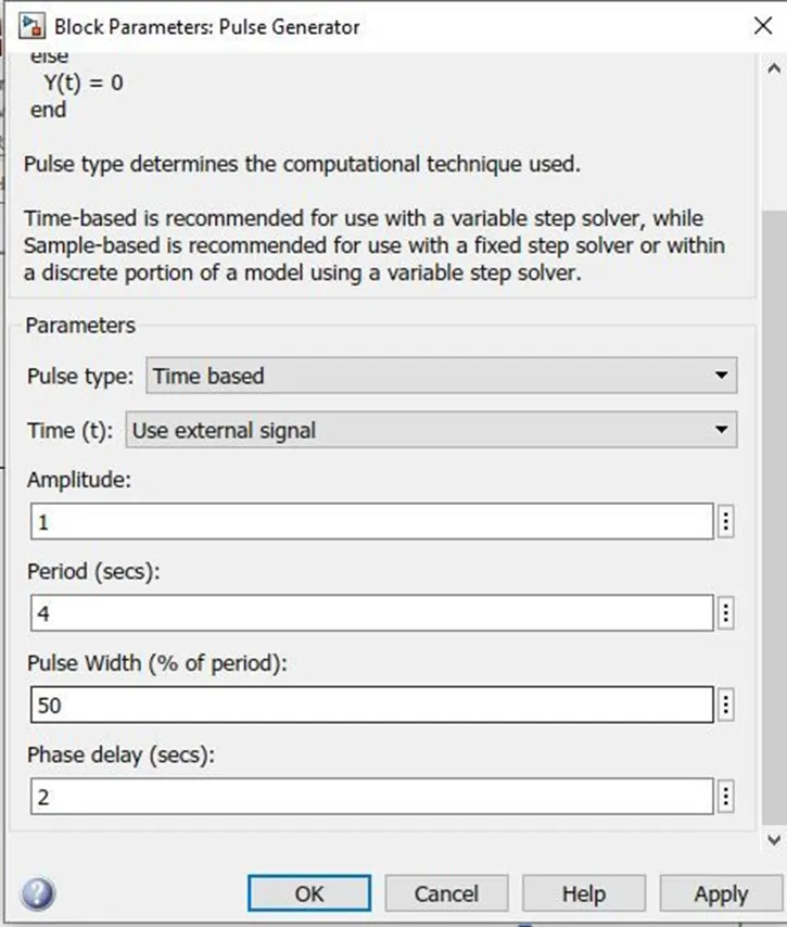
According the question, we just provide the input to pulse generator as shown in figure.
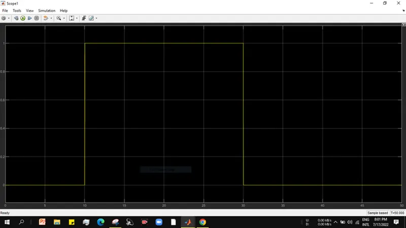
After Compiling or running the system, the input signal from Scope 1 is as shown below.
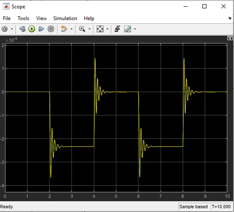
And the Output signal of system is as shown in Scope.
Output Scope
2).Use a thermistor to sense the temperature of a heater & turn on or turn off the fan as per the below conditions:
Temperature source: 20 °C from 0 to 10 seconds, 27 °C from 10 to 30 seconds, 23 °C from 30 to 50 seconds
Fan conditions: ON if the temperature above 25 °C, OFF otherwise.
ANSWER:-
Blocks used in model:
- Repeating Sequence Stair
- Controlled Temperature Source
- Thermistor
- Resistor
- Voltage sensor
- Battery
- Switch
- Lamp
- Scope
- Dsiplay
- PS-Simulink Converter
- Simulink-PS Converter
- Solver Configuration
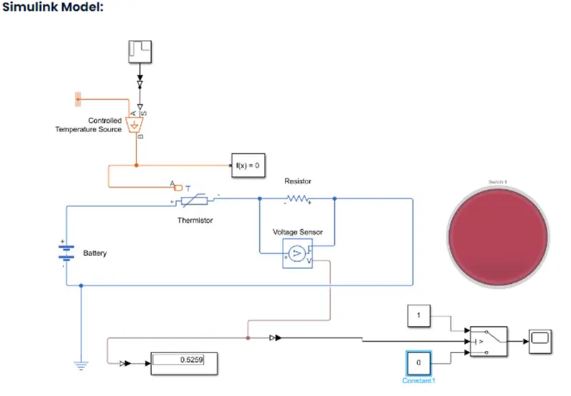
A Repeating Sequence Stair is given as input to the thermistor through a controlled temperature source. The sample time was taken as 10s and the whole simulation time was taken as 50s.Battery and a resistor is connected in the thermistor circuit. A voltage sensor was given accross this resistor to measure the voltage change during different temperature inputs. The resistance of this resistor can be set to any value, but it should not be changed once the threshold voltage is found. The threshold temperature was given as 25 degree Celsius and the corresponding voltage over the resistor was found out, through a display connected to the voltage sensor. At this time the Repeating Sequence Stair was given only one value, i.e, 25 degree Celsius or 298 K. We are choosing lamp instead of fan because i can't able connect fan with this block system.The output from the voltage was also given into a switch which is linked to a lamp which displays different colours based on the logical conditions. The lamp color was set to red if the temperature was below 298K and to green when the temperature is above 298K.
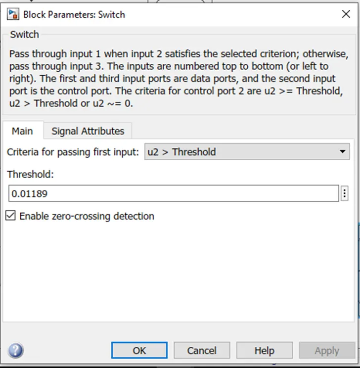
When we put threshold temperature 25 degree Celsius i.e( 273+25) 298K, we get the value the threshould voltage 0.01189 from the help of voltage sensor and display block. Therefore as per given condition, we put that value in switch threshold as shown in figure below.
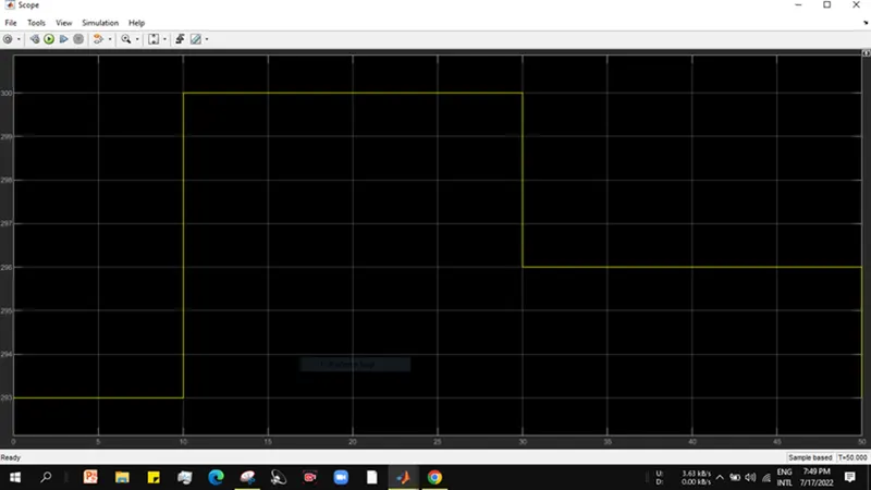
Now after compiling or running the system as per condition, the input signal is shown below scope.As we can see,0-10sec, the temperature is 293k (273+20), and then after 10-30sec, the temperature is 300k(273+27), and in last 30-50sec the temperature is 296K (273+23).
Now the output Signal is shown in below Scope1. As we can see for 0-10sec, the output is 0 which means fan is off, further 10-30sec the output is 1, which means the fan is running.Now in 30-50sec the output is again 0 means fan off at 23 degree celsius.