Week -2
- Make a Simulink model of Doorbell using solenoid block with the following details:
ANS1- Feed the input pulse generator block is created. The input for the pulse generator is given below,
Parameters of pulse generator
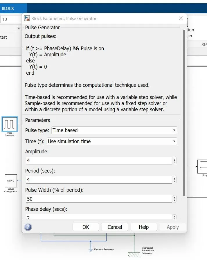
Amplitude as 4
Period sec as 4
Pulse width(%of period) as 50
Phase delay (sec) as 2
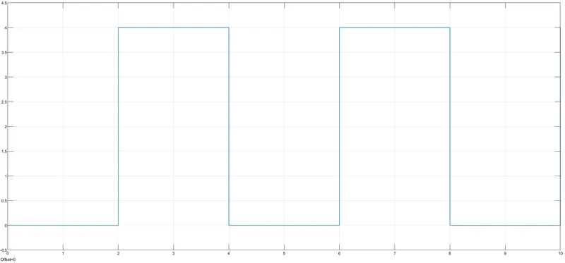
This is the input signal which is fed into the electrical circuit. The input has to be converted from the Simulink input signal to the Physical signal. This is connected to the switch.
One end of the switch is connected to the positive terminal of the battery and the other end is the negative terminal of the solenoid.
The negative terminal of the battery is then connected to the positive terminal of the solenoid. Electrical resistance is connected to the circuit and a solver configuration is also added.
The case 'C' of the solenoid is connected to the mechanical reference and the Plunger 'R' is connected to the Translational conserving ports. The Position 'P' of the translational motion sensor is connected to the output scope and display. Before this, the physical signal is converted into the Simulink signal.
OutPut

The amplitude/vibration shown at the bottom indicates the bell is ringing at the interval of 2 seconds with phase delay of 2 seconds.
The amplitude/vibration at the phase delay line is a concern in the output.
2. Use a thermistor to sense the temperature of a heater & turn on or turn off the fan as per the below conditions:
We have used following blocks in the model-
- Pulse Generator.
- Switch.
- Battery.
- Solenoid.
- Ideal Translational motor sensor.
- Mechanical translational reference.
- Electrical reference.
- Scope.
As per given conditions switch is closed for 2 seconds & then released.The pulse generator is used to create square wave pulses at regular intervals. The block waveform parameters, amplitude, pulse width, period and phase delay, determine shape of the waveform.
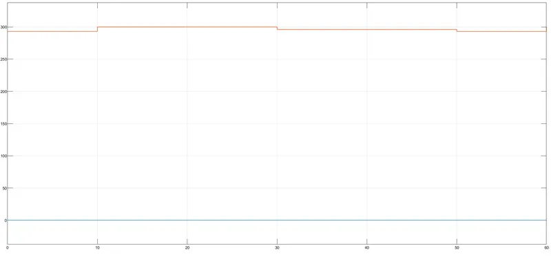
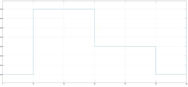
ANS2- we have make thermistor to sense the temperature of a heater & turn on or turn off the fan.We have use Repeating sequence stair in which i have attached the parameter of Repeating sequence stair.we have also measured the voltage across the resistance for which we have used voltmeter.we have kept threshold temperature 298 Kelvin,When temperature is greater than threshol temperature the FAN will be ON otherwise OFF.
INPUT
The positive side of the thermistor is connected to the positive terminal of the battery and the negative side of the terminal is connected to the voltage sensor ( which helps to detect the current flow in the circuit). This is followed by electrical resistance.
OUTPUT