Week -2
QUESTION 1
AIM : Make a Simulink model of Doorbell using solenoid block with the following details:
OBJECTIVES :
- In the above arrangement, when the switch is closed the electromagnet receives electrical power from the battery and pulls the metal arm to hit the bell producing sound.
- Create a situation where the switch is closed for 2 seconds and then released. Observe the physical movement of the plunger.
Doorbell :
- A doorbell is a siginaling device which is placed near a door to building entrance.when a visitor press a button the bell rings inside the building alert the presence of vistor.this doorbells are low voltage devices.
- When you press a doorbell button a complete an electrical circuit that allows household electricity to flow through the doorbell's internal electromagnet. The magnetic field generated by the electromagnet is then used to power a mechanism that creates the doorbell sound.
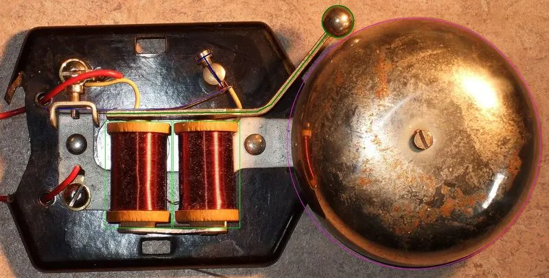
Solenoid :
- A solenoid is a device comprised of a coil of wire, the housing and a moveable plunger.When an electrical current is introduced, a magnetic field forms around the coil which draws the plunger in.
- More simply, a solenoid converts electrical energy into mechanical work.
Simulink model for doorbell using solenoid :
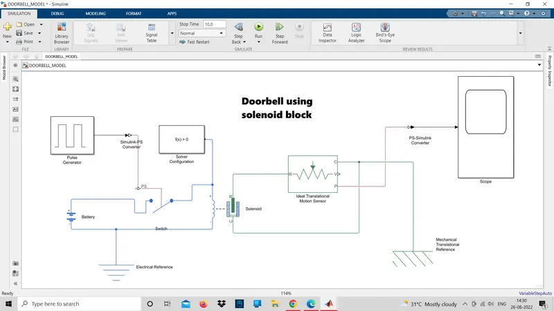
The figure above is the representation of "A doorbell operated on solenoid". In this model, some blocks are used to make the working model of the doorbell. These blocks are:
- Pulse Generator : The Pulse Generator block generates square wave pulses at regular intervals. The block waveform parameters, Amplitude, Pulse Width, Period, and Phase delay, determine the shape of the output waveform.
- Simulink-PS Converter: Converts the unitless Simulink input signal to a Physical Signal.
- Scope: Display signals generated during simulation.
- Switch: Switch controlled by an external physical signal.
- Battery: The Battery block represents a simple battery model.
- Solenoid: Model electrical characteristics and generated force of solenoid.
- Ideal Translational Motion Sensor: The Ideal Translational Motion Sensor block represents a device that converts an across variable measured between two mechanical translational nodes into a control signal proportional to velocity or position. You can specify the initial position (offset) as a block parameter. The sensor is ideal since it does not account for inertia, friction, delays, energy consumption, and so on.
- Mechanical Translational Reference: The Mechanical Translational Reference block represents a reference point, or frame, for all mechanical translational ports. All translational ports that are rigidly clamped to the frame (ground) must be connected to a Mechanical Translational Reference block.
- Electrical Reference: The Electrical Reference block represents an electrical ground. Electrical conserving ports of all the blocks that are directly connected to the ground must be connected to an Electrical Reference block. A model with electrical elements must contain at least one Electrical Reference block.
- Solver Configuration: The Solver Configuration block specifies the solver parameters that your model needs before you can begin the simulation.
- PS-Simulink Converter: Convert physical signal into Simulink output signal.
Model Explanation:
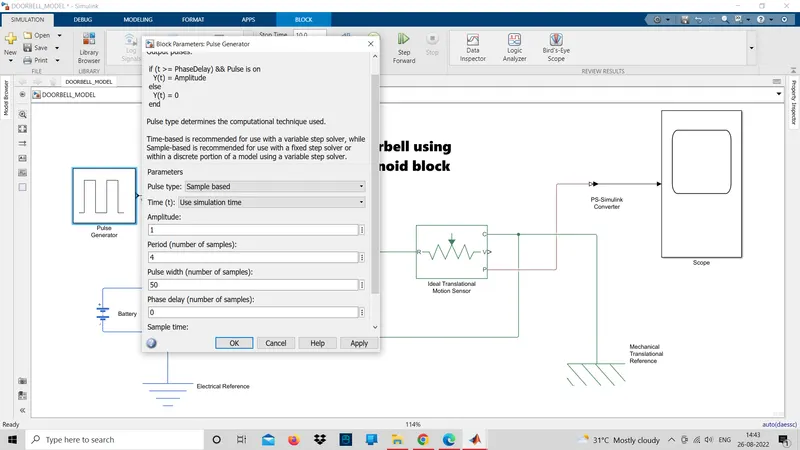
- The pulse generator is used to give the signal input where, Amplitude=1, Period=4 sec, Pulse width= 50%, and Phase delay= 2 sec.
- After that, the input signal is converted into physical form with the use of Simulink-PS Converter and further send to the switch of the electrical circuit.
- The electrical circuit consists of a solenoid, a battery, and a switch. One end of the solenoid is connected to the battery and its other end is connected to the switch. An electrical reference is provided in the electrical circuit.
- The mechanical part of the solenoid is connected to an ideal translation motion sensor and mechanical translational reference.
- The P-port of the sensor makes a connection with the PS-Simulink Converter to provide the output in signal form. Further, the converter is connected with scope to display our output signal.
- A solver configuration is connected to an electrical circuit to solve all parameters before the beginning of the simulation.
Output:
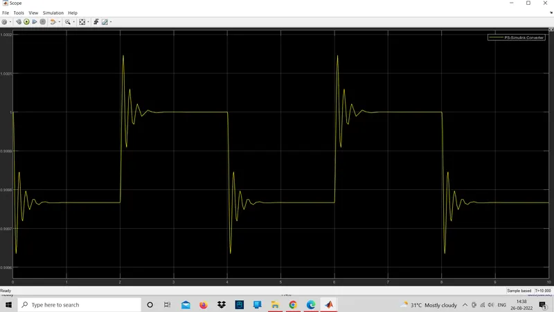
Here we can see that the switch is closed for 2 seconds and after that switch is open. Amplitude= 0 means the switch is closed. It can also be seen that the plunger strikes after every 2 seconds.
The motion of the plunger was simulated and recorded and plotted in scope.
QUESTION 2
AIM : Use a thermistor to sense the temperature of a heater & turn on or turn off the fan as per the below conditions:
OBJECTIVES :
- Temperature source: 20 °C from 0 to 10 seconds,
- 27 °C from 10 to 30 seconds,
- 23 °C from 30 to 50 seconds
- Fan conditions: ON if the temperature above 25 °C, OFF otherwise
Thermistor :
- A thermistor is a resistance thermometer, or a resistor whose resistance is dependent on temperature.
- The thermistor works on the simple principle of change in resistance due to a change in temperature. When the ambient temperature changes the thermistor starts self-heating its elements.
- its resistance value is changed with respect to this change in temperature. This change depends on the type of thermistor used.
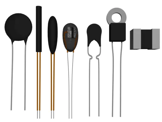
- Thermistors act as a passive component in a circuit. They are an accurate, cheap, and robust way to measure temperature. While thermistors do not work well in extremely hot or cold temperatures, they are the sensor of choice for many different applications.
Simulink model for Thermistor :
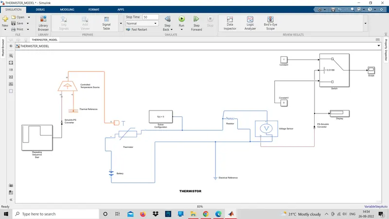
Model Explanation:
- At first, the signal is created in Repeating Sequence Stair and further passes to Simulink-PS Converter to convert the input signal into the physical signal.
- This physical signal is connected to a block Controlled Temperature Source. This block is connected to the thermistor and a Thermal Reference block.
- The thermistor is a part of an electric circuit where a battery, a voltage sensor, a resistor connected parallel to the voltage sensor, an electrical reference are connected to make a complete circuit. A solver configuration is connected to that electrical circuit to solve all parameters before the beginning of the simulation.
- The voltage sensor senses the temperature in the form of voltage and sends the data to its port "V".
- From this port, we get our output and send it to two different PS-Simulink Converter.
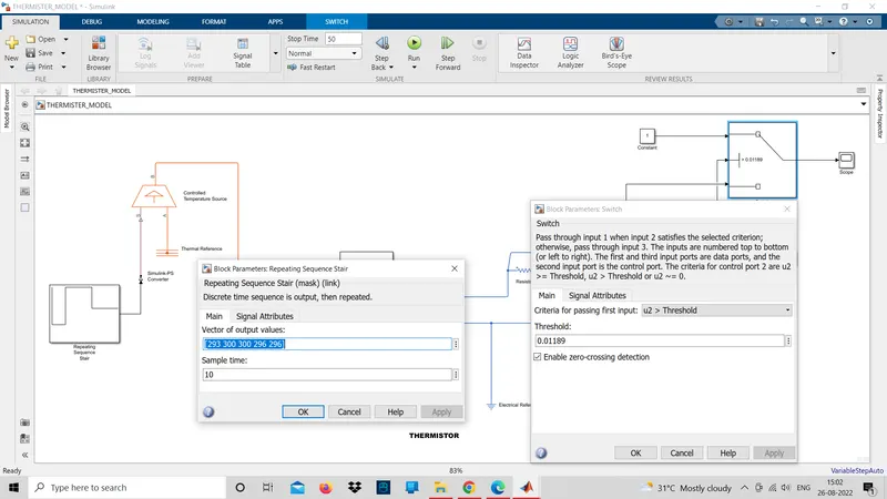
- From converter-1, the signal is sent to the threshold switch. In the switch, the threshold limit is set to 1.10555e-02. If the temperature is above or equal to the threshold limit, then it gives "1" as output which is "Switch On". If the temperature is below the threshold limit, then it will give "0" as output which means "Switch Off". The input signal is generated with the help of a Repeating sequence stair block
- The switch is connected to the scope where we can see our output plot.
- From converter-2, it converts the physical signal into a Simulink signal and sends the voltage data from the Voltage Sensor to display. This display gives us the threshold value of voltage. This value is set in the switch.
Output:
- Angular velocity:
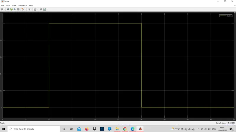
- From the above graph we can observ that if the temperature is 20 deg,celcius(293k) the fan is off for first 10 sec.
- when the temperature is 25 deg celcius (300k) then the fan is off for next 20 sec.
- And when the temperature comes to 23 deg celcius (296k)fan gets off.
Conclusion :
- In the first part of the question we use a solenoid to convert electrical energy to mechanical and prepared a simulink model into a doorbell
- In the secound part of the question we use the thermistor to sense the tempearture based on the conditions given and we aslo added threshold value to the switch for turn on and turn off the fan.