Week -2
AIM: SIMULINK MODEL OF DOORBELL USING SOLENOID.
CONDITION: When the switch is closed electrical power flows through the electromagnet from the battery and the metal arm to hit the bell producing sound.
To Observe: Switch must be closed for 2 seconds and then released
SIMULINK MODEL:
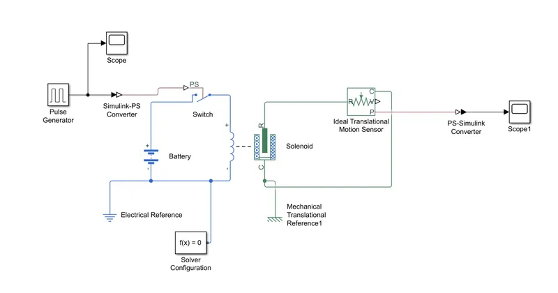
EXPLANATION:
I have used the following blocks to design the Simulink mode.
- PULSE GENERATOR:
It is used to generate square wave pulses at regular intervals. It also has few parameters like amplitude, Pulse width, period and phase delay.
- SIMULINK TO P.S CONVERTER:
This block is used for conversion, where it converts Simulink input to physical input for the physical system.
- PS TO SIMULINK:
The p.s to Simulink converter block converts a physical signal into a Simulink output signal
- IDEAL TRANSLATIONAL MOTION SENSOR:
Ideal rotational motion sensor block represents on ideal mechanical rotational motion sensor that is used to convert variable measured between two
mechanical rotational nodes into a control signal.
- SOLENOID:
Solenoid block represents the electrical character and generated force for the solenoid. Generally its length is greater than its diameter.
- ELECTRICAL REFERENCE:
It is representation of an electrical ground. A model with electrical elements must contain atleast one of them.
- WORKING
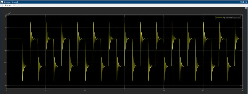
1. The main objective is to make switch on for only 2sec.This condition is achived by PULSE GENERATOR block. Where amplitude is given following by period it can also be decide with run time.where here period is 2sec and run time is 30sec the bell will be in a cycle (on and off )for 15 times
2. Phase delay is where delay time after which simulation output starts.
3. So as we do the power from the battery energises the solenoid connected to the metal arm hits the metal casing results in producing the ringing sounds.
4.As stated switch will be on condition only for 2sec then the switch is open and electrical supply is broken and solenoid and metal arm retains its orginal position same procedure is repeated again
Scope output
Result:
As observed from the above simulation model and its respective output
Simulink model satisfies the given condition.
AIM: TO DESIGN AND SIMULATE A MODEL FOR THERMISTOR TO SENSE THE TEMPRATURE OF HEATRER AND TURN OFF AND TURN ON THE FAN.
CONDITION: Temperature source: 20 °C from 0 to 10 seconds, 27 °C from 10 to 30 seconds, 23 °C from 30 to 50 seconds
Fan conditions: ON if the temperature above 25 °C, OFF otherwise
Fan must be on only for 300k and for a time period of 20sec
Celsius to kelvin
20°C = 20 +273=293 KELVIN
27°C = 27 +273=300 KELVIN
23°C = 23 +273=296 KELVIN
SIMULINK MODEL:
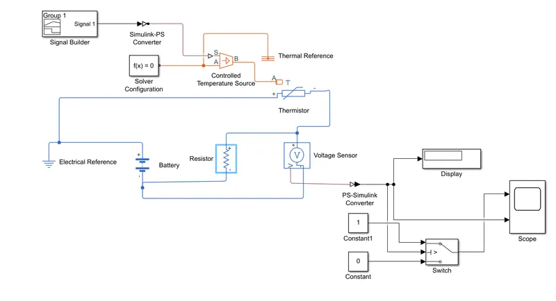
EXPLANATION:
- Signal Builder:
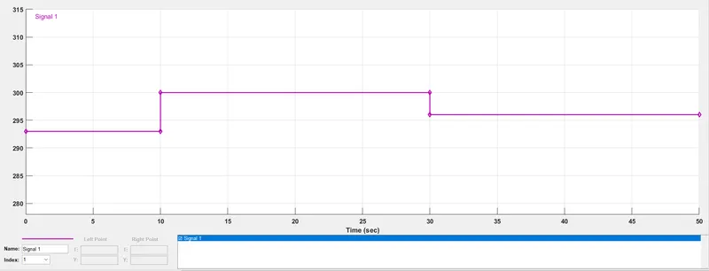
Used it to create interchangeable groups of linear and more signal sources to use in the respective model.
Where we can use time period and amplitude and define its respective output waveforms.
- Controlled Temperature Source:
Ideal source of thermal energy used to maintain temperature (specific)
ports can be used to provide the input to the blocks.
Temperature in the source is directly proportional to the signal applied.
- Thermal Reference:
A point maintained at absolute zero temperature with respect to entire system.
- Thermistor:
An electrical resistor whose resistance can be brought down by heating used for measurement and control . It is particularly sensitive to temperature.
Used in digital thermometer, automotive applications(to measure oil and coolant temperature)
Two types: NTC thermistor
PTC thermistor
- Switch:
It switches between 1 and 3 input based on the second input, where1 and 3 are data.
- Working:
- 1.Initially taking up all the conditions given. The fan must be on for the temperature of 300kelvin and time period of 10sec to 30sec.
- 2.A signal need to be builded first for the required condition. The Feedback is given to the controlled temperature source.
- 3.Source maintains the temp with regarding the signal. Where a is an thermal port of the thermistor.
- 4.As we know the thermistor characteristics. An external supply is used to powerup. We also have an voltage sensor to measure up the voltage from the thermistor for required to temperature.
- 5.To know the threshold value we can give the respective temperature values in kelvin values as an constant input to the system and note down the value. Which can be viewed in the display block.
- 6.Finally when the signal builder provides output to the system the result is obtained and output can be viewed in scope block.
- OUTPUT
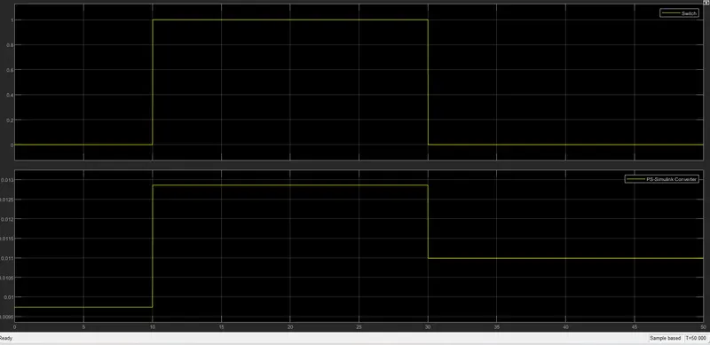
- RESULT
As observed from the above simulation model and its respective output Simulink model satisfies the given condition.