Week -2
Answer 1
Simulink model of a Doorbell using a solenoid block.
A electrical doorbell, primarily uses electrical current for its function. It means, inside the package of a bell, there is a switch, which put itself on and off when the current passes through it. This on and off is controlled by a pulse regulator, which can be coded to be switched on and off, for a certain duration of time, as we need the bell to be functioned.
Here instead of AC electrical source, we are using a battery, which operates the doorbell. However, to operate the bell, to be rung, an electromagnetic force needs to be generated which will eventually make the hammer vibrate in a harmonic sin wave, so that it can hit and loose the gong, in a periodic manner. This electromagnetic source is the solenoid. The solenoid is nothing but a cylindrical piece of iron coiled with nickel or copper and on passing of current, act as an electromagnet. This is connected with the metal strip which has a small hammer at the bottom and the other end is connected with a switch, that actuates as per the current passed through it. The pulse generator is connected with this switch, which controls the pulsating current that passes through the switch from the battery and makes it go on-off-on-off in a waveform.
The situation provided in the question is to observe the physical behaviour of the Plunger (hammer) in case of the condition, where the switch is kept closed for 2 seconds and then released.
Physical setup
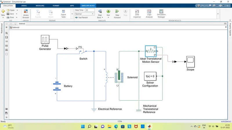
In the simulink environment, each block has to be arranged in a manner, that reflects the actual physical setup of the solenoid based doorbell system. If we iterate them in the correct order of arrangement, the following blocks will be required
1. Battery.
2. Switch.
3. Pulse Generator (regular or continous)
4. Solenoid
5. Ideal Translational Motion sensor (To measure relative velcoity and displacement of the plunger)
6. Solver configuration, PS-Simulink converters and Scope blocks
The above blocks can be arranged in the model displayed below
Simulink Model
Pulse Configuration
The below figure and input snapshot explains the required input to be kept so as to satisfy the necessary challenge of the question.
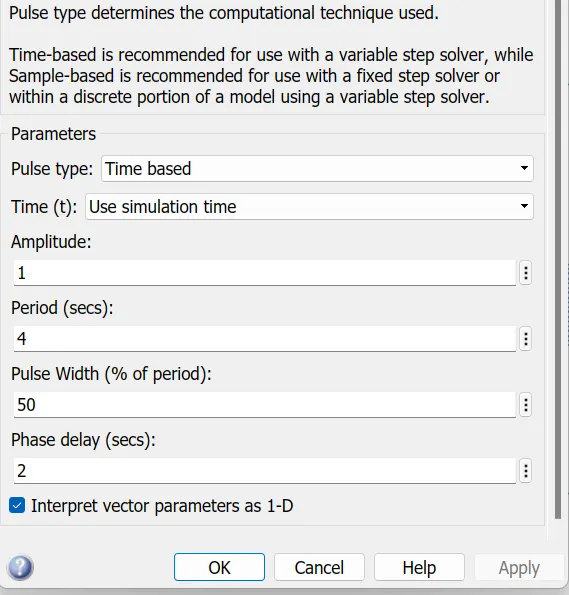
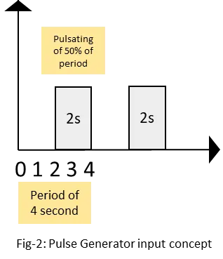
Based on the above input and the arrangement of the simulink environment, the following output of pulsating plunger is observed.
Result:
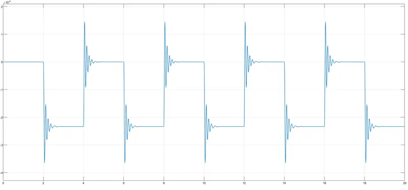
Here, as the pulse time is of 2s and Period is of 4s, runtime of simulation is taken to be t=20s, so as to see the result over a larger timespan.
Answer -2
Aim: To turn the fan of the heater on and off, based on temperatures achieved by the heater in a specific time using a Thermistor.
Objective: understand and develop a simulink environment, to code the thermistor as per the necessary requirement as given.
| Time | Temp (C) | Fan | |
| 1 | 0-10 | 20 | Off |
| 2 | 10-30 | 27 | On (25C) |
| 3 | 30-50 | 23 | Off |
Solution
A thermistor is a electrical component, whose resistance varies with the change in temperature and hence, is kept within the electronic circuit in such a position, where it can be used to cut the circuit on or off, based on temperature achieved by a specific electrical or electronic device.
There are mainly 2 types of thermistors NTC(Negative Temperature Coefficient) and PTC(Positive Temperature Coefficient). In NTC, if temperature increases, resistance decreases and if temperature decreases, resistance increases. In short temperature and Resistance are inversely proportional.
In PTC the Temperature rises, resistance rises and Temperature reduces resistance decreases. Temp and Ohm are directly proportional.
First of all we need to establish parameters based on the requirement.
Thermistor resistance, input signal attributes, switching sequence and a rotational
Thermistor resistance is considered 82.9 ohm;
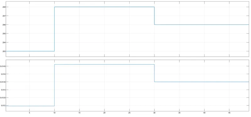
Input signal attributes using repeating sequence stair block, with 10 s time steps and using temperature as given in kelvin
20degree celcius to 293 kelvin
25degree celcius to 298 kelvin
23degree celcius to 296 kelvin
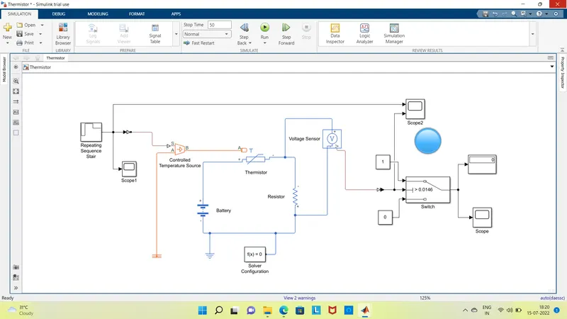
Switching sequence using repeating sequence stair and controlled temperature source block connected to the Thermistor having R= 1000 ohm, and T0 = 293 Kelvin. The Thermistor connected to voltage sensor, as the sensor will sense the voltage difference, once the temperature rises from 293 k to 298 k, where the Fan shall start functioning. The voltage at this stage will be 0.0146V
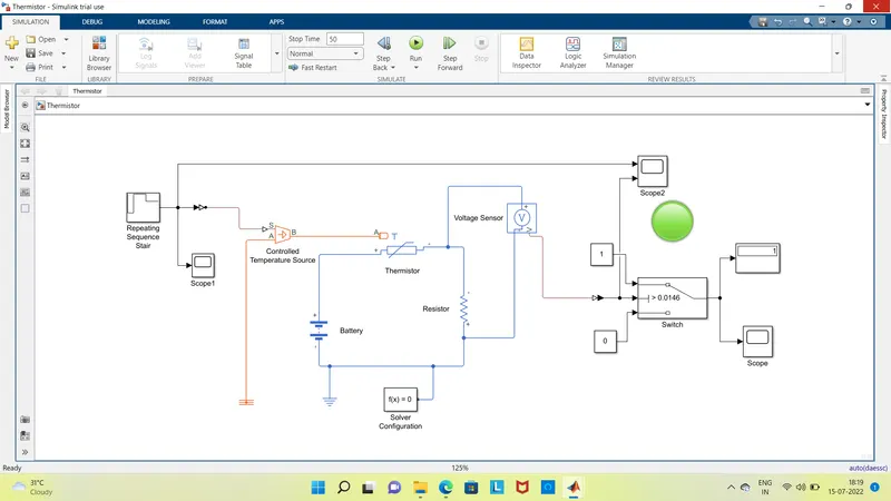
Once the Fan starts functioning, the temperature will come down to 296K and the Voltage again will drop down to 0.0135V, which will turn off the fan.
This arrangement within the simulink environment as well as its results are explained in the following figures and charts.
Scenario -1 : When the voltage reaches 0.0146V and the fan switches on.
Scenario -2: When the voltage drops down to 0.0135V as the fan cuts off
Resultant voltage difference wrt the Temp. input differences.
Conclusion:
The differences in the temperature, is sensed by using a controlled temperature source, which helps in fluctuating required temperature and helps the thermistor to act accordingly. The Voltage sensor will sense this changing temperature and help the fan to put itself on and off as per the temperature input and conditions.