Week -2
Question 1
solution:
Theory:
Door Bell:
A doorbell is a signalling tool frequently located close to an entrance door to a structure. A bell within the building sounds when a visitor touches a button, alerting the occupant to the visitor's presence. An electromagnet is a doorbell's beating heart. Coils of wire are wrapped around a tiny magnetic metal component to create an electromagnet. A magnetic field forms around a wire when electricity flows through it. By pressing a doorbell button, you complete an electrical circuit that enables household energy to pass via the magnetic inside the doorbell. The doorbell sound is then produced by a mechanism that is powered by the electromagnet's magnetic field.
Devices with low voltage are doorbells. This means that they operate with comparatively minimal energy. The transformer is a crucial component of a doorbell system. The transformer changes the standard 120-volt home current into the lower voltage needed by the doorbell, which is typically between 6 and 16 volts.
Solenoid:
A solenoid is a three-dimensional wire structure. This wire exhibits some unique magnetic properties when electricity is applied to it when it is wound around a metallic block in a coil. It becomes an electromagnet that can be turned on or off thanks to electromagnetic induction. The South Pole is the side in which the current appears to be flowing clockwise, and the Northern Pole is the side in which it appears to be flowing counterclockwise. The solenoid has numerous applications since it functions just like a bar magnet. Among other things, valves are made using this theory. It is a relay in places where a solenoid would drive an electric switch.
The blocks used in the formation of doorbell are:
- Pulse Generator: The Pulse Generator block generates square wave pulses at regular intervals. The block waveform parameters, Amplitude, Pulse Width, Period, and Phase delay, determine the shape of the output waveform.
- Simulink-PS Converter: Converts the unitless Simulink input signal to a Physical Signal.
- Scope: Display signals generated during simulation.
- Switch: Switch controlled by an external physical signal.
- Battery: The Battery block represents a simple battery model.
- Solenoid: Model electrical characteristics and generated force of solenoid.
- Ideal Translational Motion Sensor: The Ideal Translational Motion Sensor block represents a device that converts an across variable measured between two mechanical translational nodes into a control signal proportional to velocity or position. You can specify the initial position (offset) as a block parameter. The sensor is ideal since it does not account for inertia, friction, delays, energy consumption, and so on.
- Mechanical Translational Reference: The Mechanical Translational Reference block represents a reference point, or frame, for all mechanical translational ports. All translational ports that are rigidly clamped to the frame (ground) must be connected to a Mechanical Translational Reference block.
- Electrical Reference: The Electrical Reference block represents an electrical ground. Electrical conserving ports of all the blocks that are directly connected to the ground must be connected to an Electrical Reference block. A model with electrical elements must contain at least one Electrical Reference block.
- Solver Configuration: The Solver Configuration block specifies the solver parameters that your model needs before you can begin the simulation.
- PS-Simulink Converter: Convert physical signal into Simulink output signal.
Simulink Model:
Pulse Generator:
Input Signal:
Output:
Explaination of the Model:
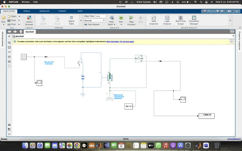
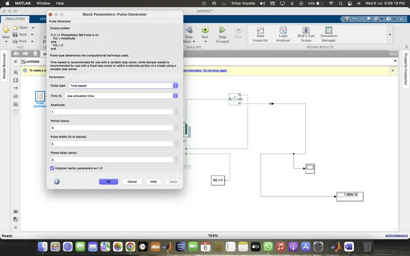
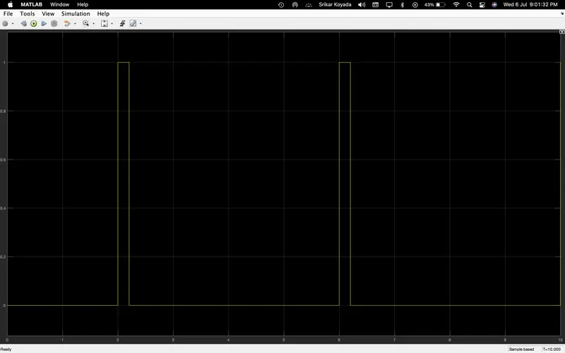
- The pulse generator is used to give the signal input where, Amplitude=1, Period=4 sec, Pulse width= 50%, and Phase delay= 2 sec.
- After that, the input signal is converted into physical form with the use of "Simulink-PS Converter" and further send to the switch of the electrical circuit.
- The electrical circuit consists of a solenoid, a battery, and a switch. One end of the solenoid is connected to the battery and its other end is connected to the switch. An electrical reference is provided in the electrical circuit.
- The mechanical part of the solenoid is connected to an ideal translation motion sensor and mechanical translational reference.
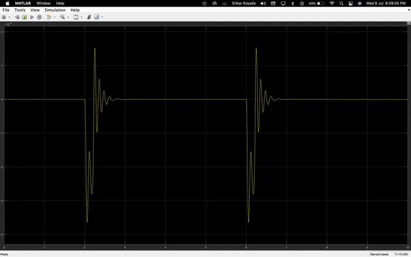
- The P-port of the sensor makes a connection with the "PS-Simulink Converter" to provide the output in signal form. Further, the converter is connected with scope to display our output signal.
- A solver configuration is connected to an electrical circuit to solve all parameters before the beginning of the simulation.
Question 2
Solution:
Use a thermistor to sense the temperature of a heater & turn on or turn off the fan as per the below conditions:
Temperature source: 20 °C from 0 to 10 seconds, 27 °C from 10 to 30 seconds, 23 °C from 30 to 50 seconds
Fan conditions: ON if the temperature above 25 °C, OFF otherwise
Theory:
A resistor whose electrical resistance changes with temperature is known as a thermistor (also known as a thermal resistor). A thermistor is highly sensitive to temperature fluctuations even though the resistance of all resistors will fluctuate slightly with temperature.
Thermistors function as a circuit's passive element. They are a reliable, economical, and accurate method of measuring temperature. The preferred sensor for many different applications, thermistors do not perform well in excessively hot or cold temperatures.
The blocks used in this model are:
i)Signal builder:
Inputs are given to the signal builder according to the given conditions
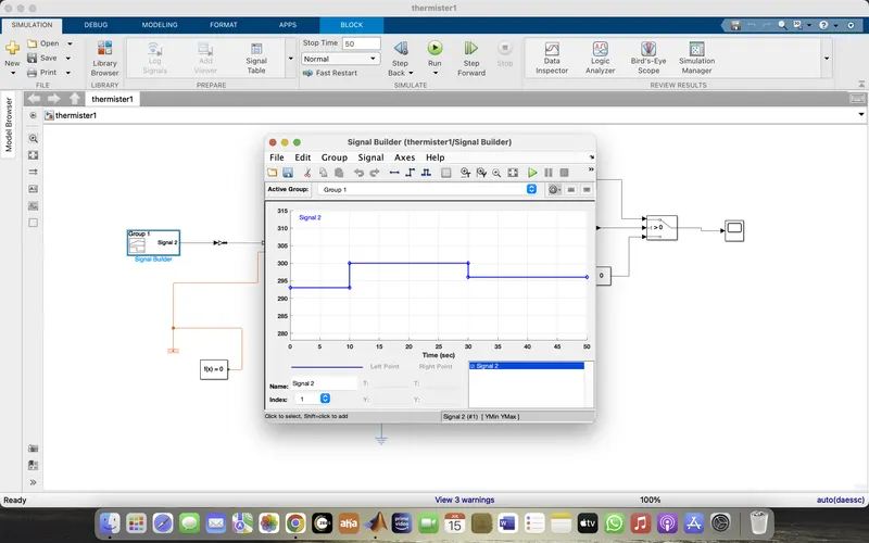
Given Inputs:
At Point1 - Time 0 sec - Temperature - 293K,
At Point2 - Time 10 secs - Temperature - 293K,
At Point3 - Time 10 sec - Temperature - 300K,
At Point4 - Time 30 sec - Temperature - 300K,
At Point5 - Time 30 sec - Temperature - 296K,
At Point6 - Time 50 sec - Temperature - 296K.
ii) Controlled temparature source:
The Controlled Temperature Source block represents an ideal source of thermal energy that is powerful enough to maintain specified temperature difference across the source regardless of the heat flow consumed by the system.
Connections Aand B are thermal conserving ports corresponding to the source inlet and outlet, respectively. Port S is a physical signal port, through which the control signal that drives the source is applied.
iii)Thermister:
A thermistor is a type of resistor whose resistance is dependent on temperature, more so than in standard resistors. The word is a combination of thermal and resistor.
The Thermistor block represents an NTC thermistor using the B-parameter equation.
NTC - Negative Temperature Co-efficient
iv)Resister:
The Resistor block models a linear resistor, described with the following equation
v)Voltage sensor:
The Voltage Sensor block represents an ideal voltage sensor, that is, a device that converts voltage measured between two points of an electrical circuit into a physical signal proportional to the voltage.
vi)Voltage source:
The Voltage Source block implements a voltage source with DC, AC, and noise components.
vii)Electrical refrence:
The Electrical Reference block represents an electrical ground. Electrical conserving ports of all the blocks that are directly connected to ground must be connected to an ElectricalReference block. A model with electrical elements must contain at least one Electrical Reference block.
Simulink Model:
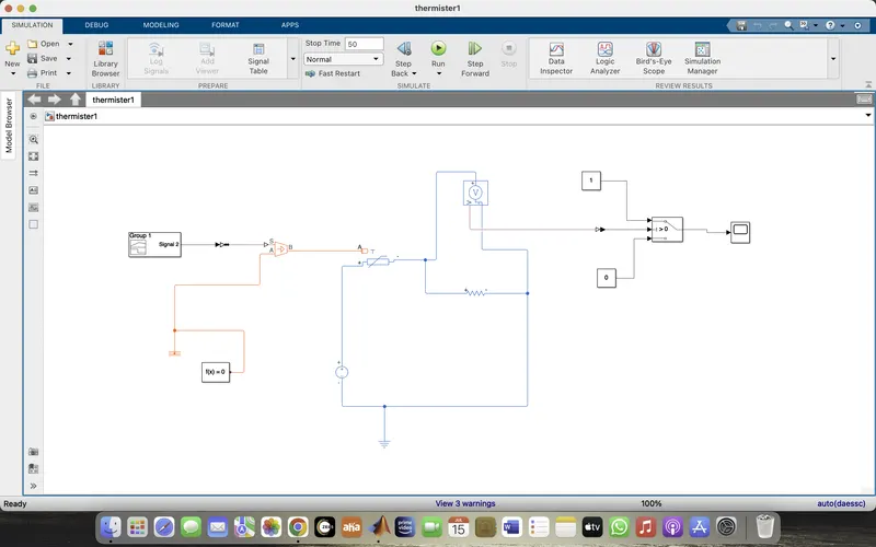
Explaination of the model:
To maintain the desired temperature difference across the source, inputs are sent to the signal builder, which is connected to a temperature-controlled source. Then the thermistor receives the input temperature.
The sign of the current is positive when flowing through the device from the positive to the negative terminal. Thermistor is linked with Resistor. Ensure that thermistor connected with positive terminal of the resistor and the voltage across the resistor is supplied by V(+) - V(-). The power absorbed by a resistor is always positive thanks to this convention. To obtain readings from the voltage sensor using a series connection, connect the positive terminal of the voltage source to the positive terminal of the thermistor and the negative terminal to the negative terminals of the voltage sensor and the resistor.
Output terminal of the voltage sensor is connected with Switch.Using the Switch Parameter for giving the condition as Fan must be ON if the temperature above 25 °C, OFF otherwise. Output is Successfully executed by connecting with scope as per the given condition.
OUTPUT:
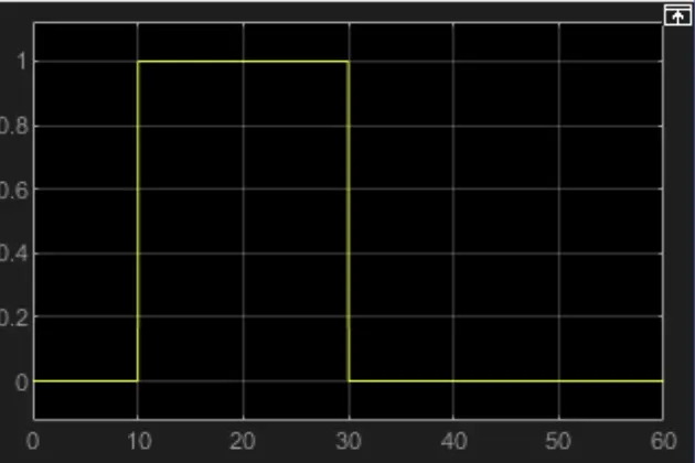
For 0-10 secs fan is in OFF condition, because temperature is 293K which is below 298K. After 10 secs temperature goes to 300K, so fan will turn ON, because temperature exceeds 298K. After 30 secs fan will turn OFF because temperature goes to 296K which is below 298K.
From the above results the given condition has been acheived and succesfully executed.