Week -2
OBJECTIVE:
1)To make a Simulink model of doorbell using a solenoid block and creating a situation where the switch is closed for 2 seconds and then released.
2)With the help of a thermistor to sense the temperature of a heater and turn on or off the fan according to the following conditions:
Temperature source: 20 °C from 0 to 10 seconds, 27 °C from 10 to 30 seconds, 23 °C from 30 to 50 seconds
Fan conditions: ON if the temperature above 25 °C, OFF otherwise.
PROCEDURE:
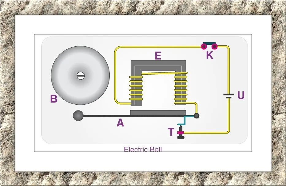
- An electric source for example a battery can be used to power the electromagnet used in an electric bell.
- The circuit is closed by connecting a switch and it helps to generate the sound while pressing it. The switch also acts as the circuit breaker.
- The circuit loop gets completed once the switch is pressed and it causes the current flow through the circuit.
- The arm which strikes the gong is connected with a spring at one end and an iron ball at the other end.
- The arm is attached to an iron strip which is attracted to the electromagnet when the circuit is complete and the current flowing through it.
- The magnetic field created by the electromagnet attracts the iron strip towards it when the circuit is complete.
- Due to this striking of the gong by the hammer, the sound can be heard.
- This process of striking keeps continuing until the switch is released.
- When the switch is released the circuit gets open and the current doesn't flow through the circuit and so the magnetic field is not created and so the hammer won't strike the gong.
SIMULINK BLOCK DIAGRAM:
- The same above procedure is practiced in Simulink by using the Simulink blocks.
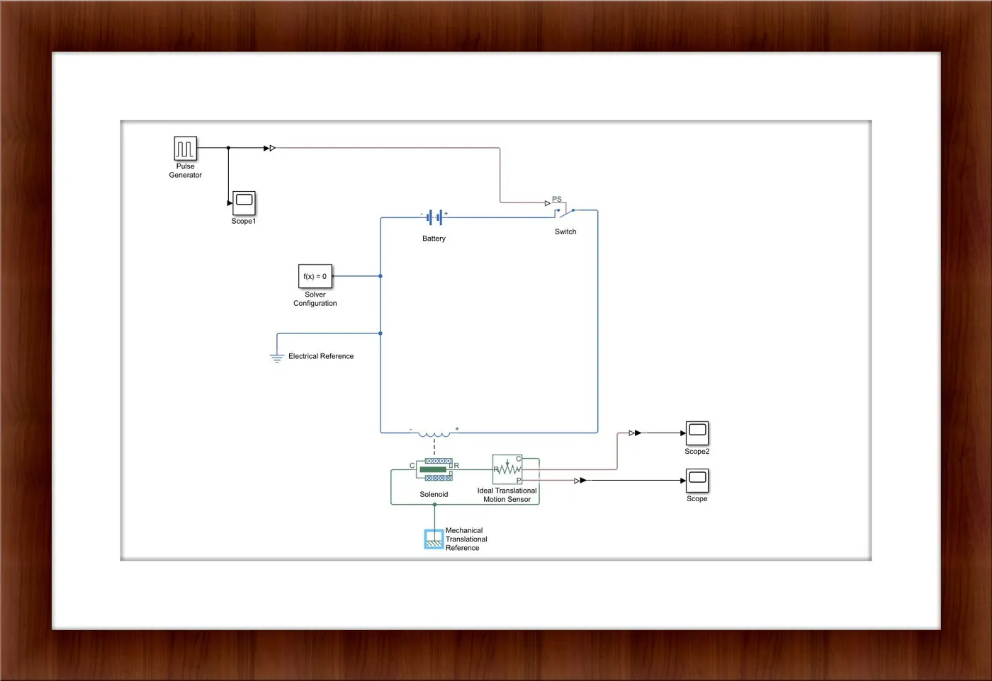
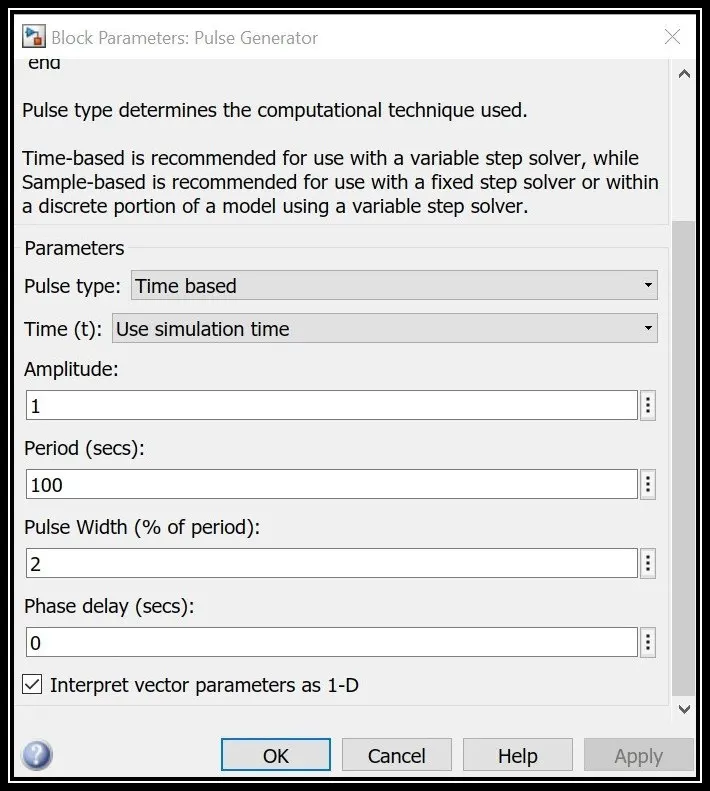
- In order to satisfy the given condition (ie for 2 sec the switch must be closed) we use a pulse generator to given as input to the model.
- In the pulse generator, we convert the period and pulse width according to the required conditions.
- The term period refers to the completion of one cycle and the pulse width refers to the percentage of pulse period that the signal is on if time-based or the number of samples if sample-based.
- The period is set as 100 sec and so the width is set as 2% which indicates that 2 sec it will be in closed and the remaining 98 sec it will be in on condition.
- We have provided pulse generator as input signal which is Simulink type so we need to convert that in terms of physical system signal so we use the Simulink-ps converter block in the next step.
- We use a switch in the next step, the circuit gets closed when it is pressed and it will be open when it is released.
- An electric source battery is used here in order to power the electromagnet.
- In Simulink, we don't have an exact gong and hammer instead we can use a solenoid for that.
- A solenoid is a generic term for the coil of wire used as an electromagnet.
- The solenoid is a device that converts electrical energy into mechanical energy.
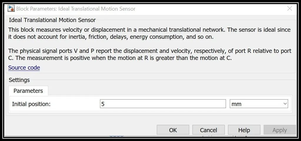
- The motion of the plunger in the solenoid can be measured using a translational motion sensor.
- To measure the movement of the plunger towards the bell, the initial position is set as 5mm.
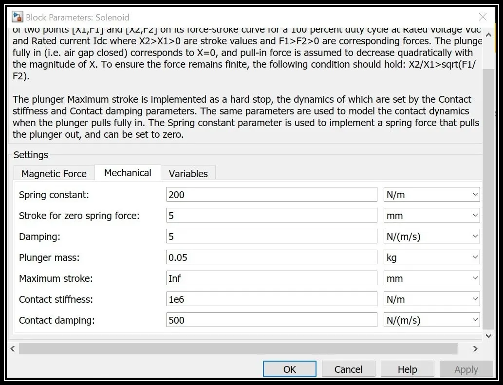
- In the solenoid block, we need to make certain changes as per our required conditions which include changing the damping value.
- Damping can be adjusted in order to restrict the oscillations.
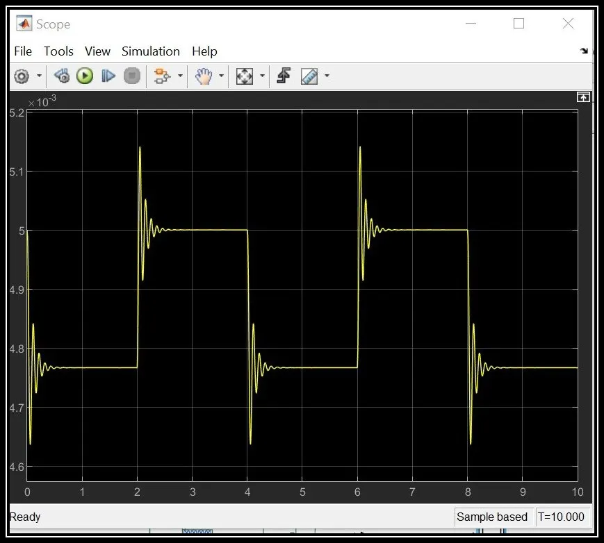
- In order to reduce these kinds of oscillation damping value can be increased.
- Based on our problem we need to close the switch for about 2 seconds so in order to keep the switch must be closed for 2 sec we increase the damping value in the solenoid block and so the oscillations are reduced.
- solver configuration is connected in the circuit based on which only the Simulink model solves our physical system.
- Then the electrical and mechanical references are connected in the circuit.
- Then run time has to be set and run the simulation by clicking the run command.
- In order to view the outputs for the entire cycle, the scope block is attached to the pulse generator in order to view the input signal and on the p port and v port in a translational motion sensor in order to view the displacement and the velocity.
RESULTS:
The Input signal to the system is as follows:
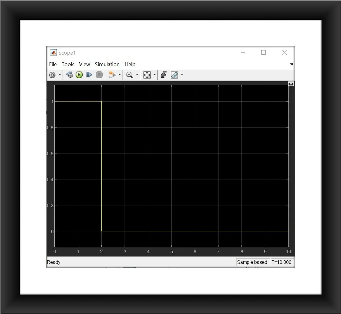
- For the initial 2 seconds, the circuit is closed and the bell rings for 2 sec and so the amplitude of the graph goes to 1 and for the rest, the circuit will be in open condition and hence the magnetic field is not generated and so the plunger in the solenoid doesn't move, and the bell ringing stops and this cycle.
The Displacement graph can be obtained as follows:
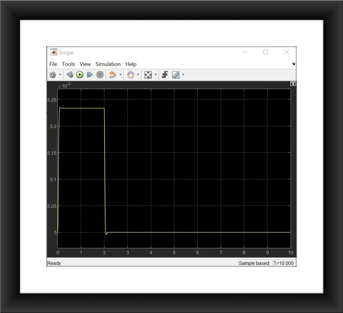
- For the initial 2 seconds, the plunger moves toward the bell and starts ringing the bell and for the rest of the period, it comes back to its initial position which is 5 mm. This kind of displacement motion is observed using the translational motion sensor for about 10 seconds.
The Velocity graph obtained as follows:
- For the initial 2 seconds, the plunger gets triggered due to the flow of current and so a magnetic field is generated due to which the solenoid gets actuated and its velocity can be observed for the using scope block. Due to the spring effect, the hammer returns back to its initial position with greater velocity. For the rest, the circuit will be in open condition, the magnetic field is not generated and due to which the velocity is zero for the rest of the period.
2)Thermistor to sense the temperature of a heater and turn on or turn off the fan as per conditions:
Temperature source: 20 °C from 0 to 10 seconds, 27 °C from 10 to 30 seconds, 23 °C from 30 to 50 seconds
Fan conditions: ON if the temperature above 25 °C, OFF otherwise
THERMISTOR:
- A Thermistor is a resistance thermometer or a resistor whose resistance is dependent on temperature.
- The term is a combination of "Thermal" and "Resistor".
- It is made of metallic oxides pressed into a bead, disk, or cylindrical shape and then encapsulated with an impermeable material such as epoxy or glass.
- There are two types of thermistors: Negative Temperature Coefficient(NTC) and Positive Temperature Coefficient(PTC).
- With an NTC thermistor, when the temperature increases, resistance decreases. Conversely, when the temperature decreases, resistance increases.
- In contrast to NTC, PTC thermistors work when the temperature increases resistance increases, and if temperature decreases, the resistance also decreases.
- Here in our model, we use an NTC thermistor we need to switch on the fan when the temperature increases.
SIMULINK MODEL:
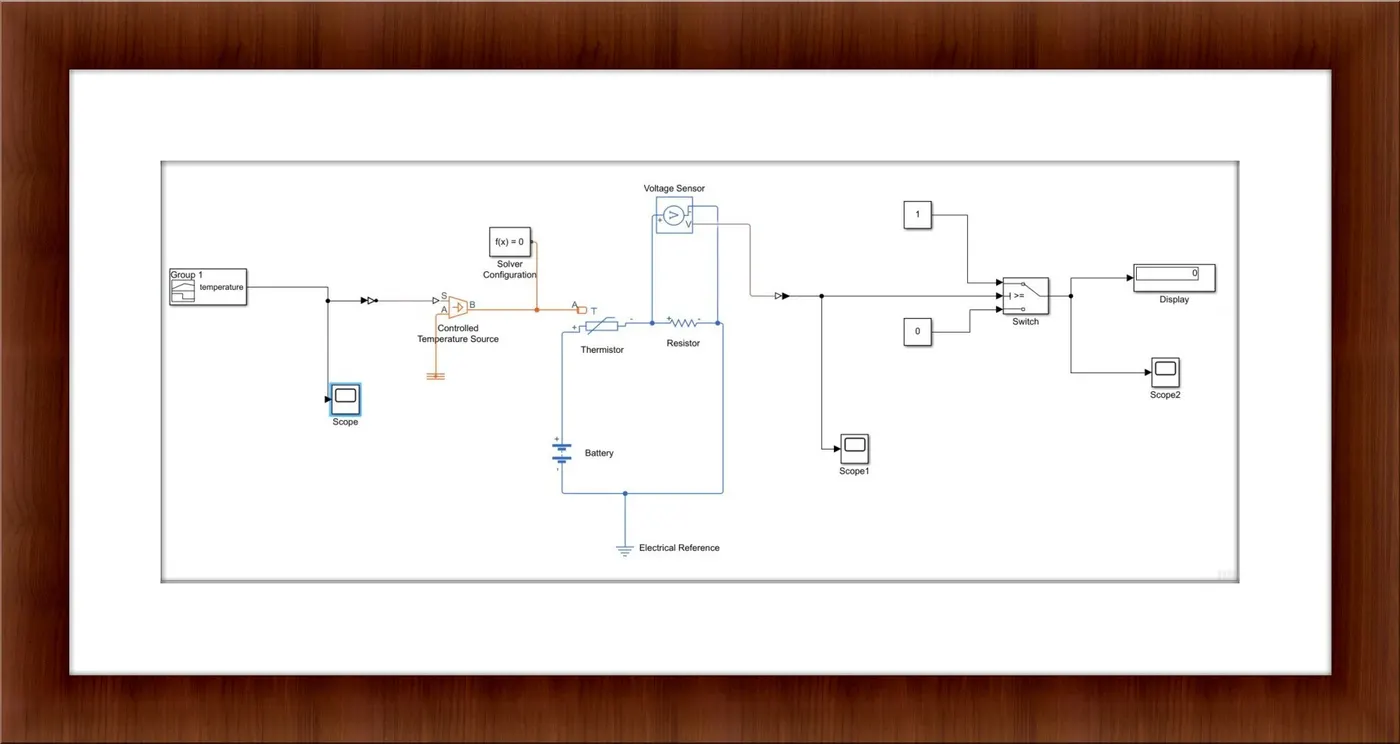
- The temperature is varying with respect to time in our problem. So we use a signal builder to generate a different signal for a particular time.
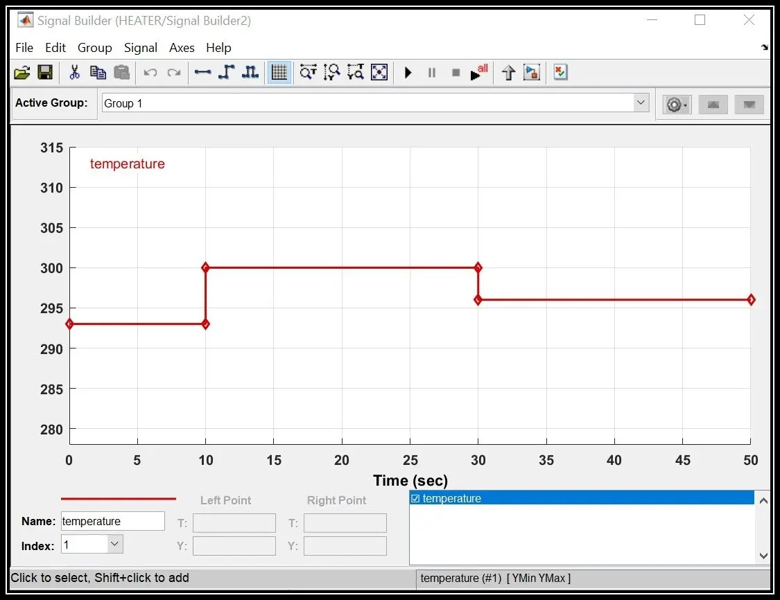
- Based on the conditions given, the temperature is 293K for an initial 10 seconds then it increases to 300K for up to 30 seconds then it reduces to around 296K up to 50 seconds.
- This condition is plotted as follows in the signal builder block.
- Then to convert this Simulink signal into a physical signal we use the Simulink-ps converter block.
- A scope attached in order to view the input temperature source.
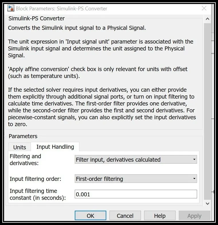
- In the Simulink-ps converter, we change the filtering and derivatives option into filter inputs derivatives calculated because our input signal varies with time so we change this option.
- Then the input from the Simulink-ps converter is connected to the S-Port of the Controlled Temperature source.
- Then the A-Port in the controlled temperature source is connected to the thermal reference.
- Then the output from the B-Port is connected to the Thermistor block.
- Due to the varying temperature in the thermistor, the resistance gets altered in the thermistor.
- In order to calculate varying resistance value, a resistor is connected in series with the thermistor.
- To measure the varying resistance voltage is measured across the resistor with the help of a voltage sensor.
- An energy source battery is connected and the circuit gets closed.
- Then the signal is converted into Simulink type in order to view in the output it is converted using ps-Simulink converter block.
- Then a scope block is attached in order to view the output voltage.
- The output from the voltage sensor is sent to the switch with the signal routing type.
- Two constant blocks with value 1 and 0 is attached to the switch.
- This type of switch will act as an if or else condition type.
- Based on the threshold value if it is greater it will display 1 else it displays 0 (ie to satisfy our condition if the temperature is above 298K the fan will be on).
- Initially, in order to set this threshold value, a single input source of about 298K is sent and the output of the voltage is noted and this noted voltage value is the threshold limit for our problem.
- The output from the witch is connected to the display block and scope in order to view it.
- The Electrical reference, thermal reference, and solver configuration blocks are all connected and the stop time is set as 50 and run the simulation by the run command.
RESULTS:
The Input signal is as follows:
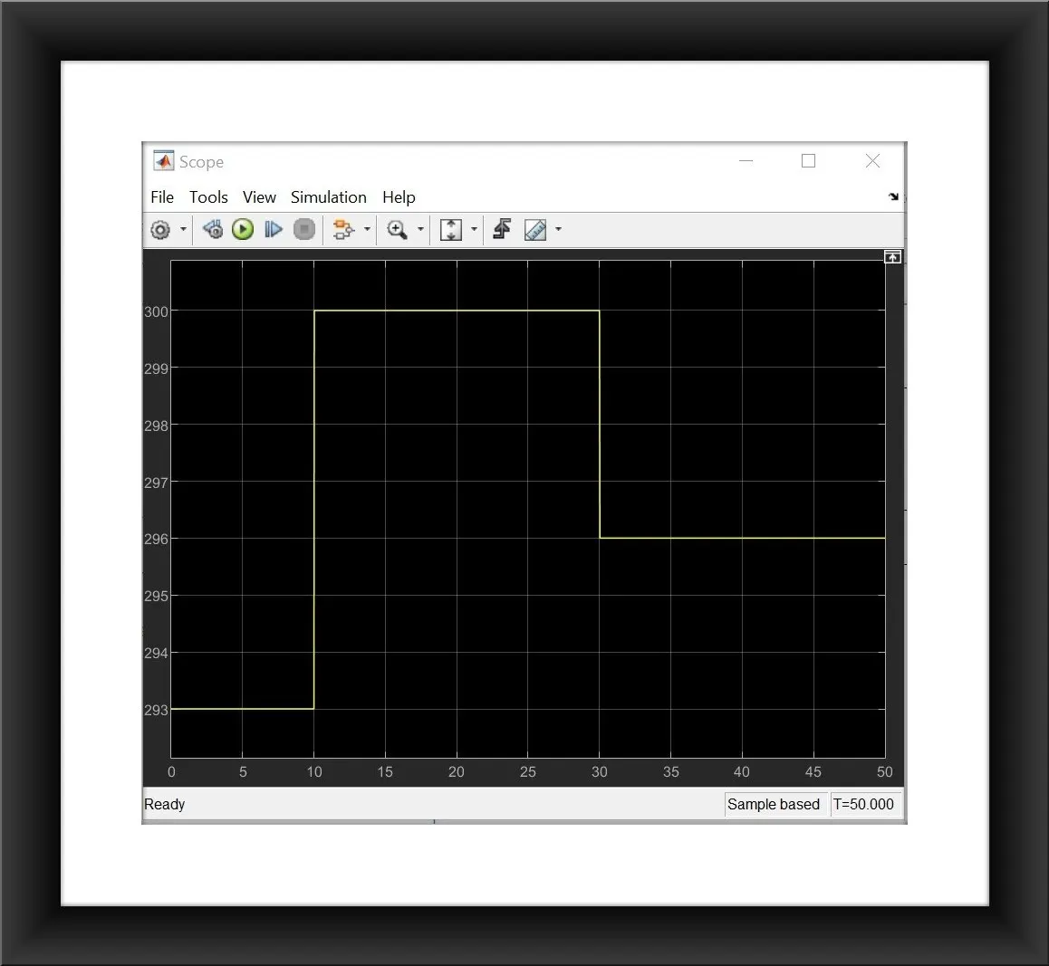
- The input satisfies the conditions such as for the initial 10 seconds the temperature is 293K, then it increases to 300K for 30 seconds, and then it reduces to 296K up to 50seconds.
- This graph confirms that the input parameters satisfy the conditions given.
The Voltage output is observed as follows:
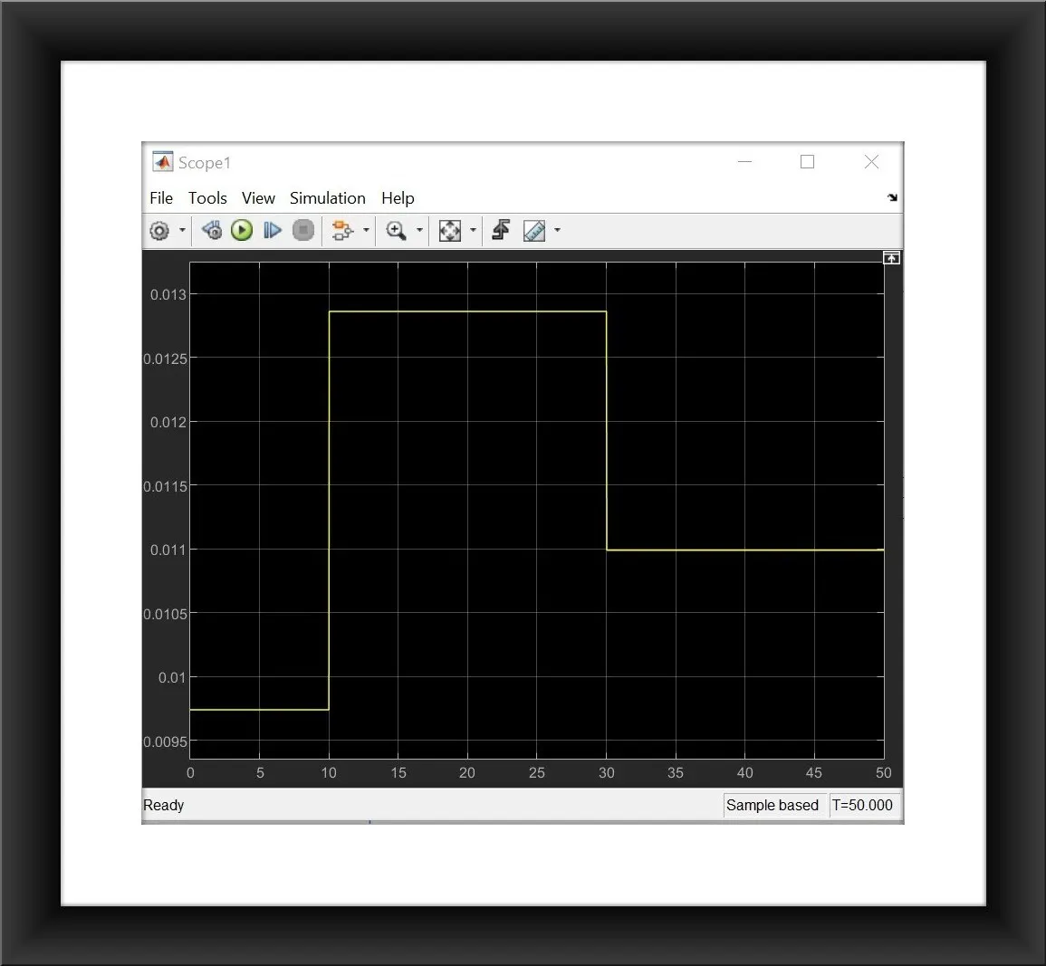
- The threshold voltage is 0.012V and so during the time period from 10 seconds to 30 seconds the fan will be turned on. The voltage remains constant at 0.0098V for the initial 10 seconds and it increases up to 0.0127V from 10 seconds to 30 seconds and again it decreases and remains constant at about 0.011V.
The Fan On/Off condition is as follows:
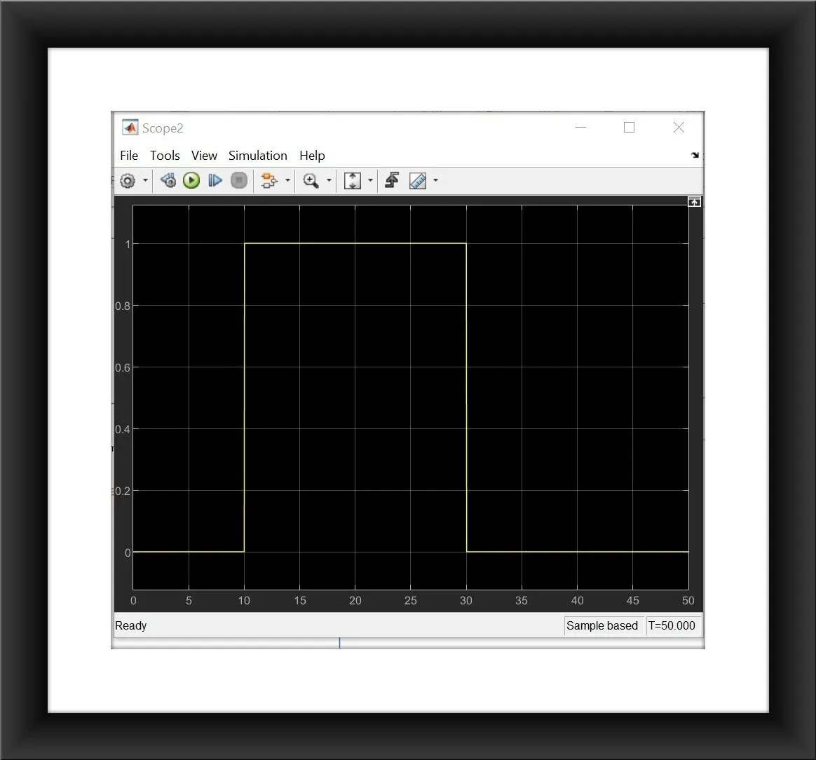
- This graph indicates that the fan is in off condition for up to 10 seconds because the temperature is less than the required condition.
- Then from10 seconds to 30 seconds the fan is in on condition which is indicated by the amplitude of 1.
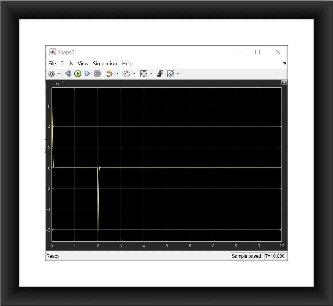
- Then from 30 seconds to 50 seconds again the conditions fail and so the fan gets off which is indicated by the amplitude reduces to zero.