Week -2
Answer 1 Explanation:
For this question we are required to set up the simulink and simscape block for the solenoid doorbell model.
The block involved are as follows:
1. PS-Simulink Converter:

Converts the input Physical Signal to a Simulink output signal.
Format of Simulink output signal matches the format of Physical Signal. 'Vector format' provides an option for outputting vector Physical Signals as Simulink 1-D arrays.
The unit expression in 'Output signal unit' parameter must match or be commensurate with the unit of the Physical Signal and determines the conversion from the Physical Signal to the Simulink output signal.
2. Simulink-PS Converter:

Converts the Simulink input signal to a Physical Signal.
The unit expression in 'Input signal unit' parameter is associated with the Simulink input signal and determines the unit assigned to the Physical Signal.
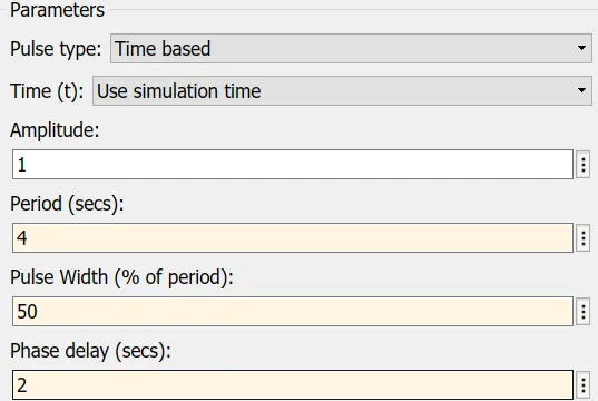
3. Pulse Generator:
It is an analog input that has amplitude and frequency with which the input is transmitted.
if (t >= PhaseDelay) && Pulse is on
Y(t) = Amplitude
else
Y(t) = 0
end
Pulse type determines the computational technique used.
4. Battery:
It is a device that has a negative and positive terminal for the electric circuit to be completed for an electric flow.
5. The Switch:
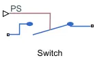
It is a device that completes the electric circuit for current flow and can be controlled manually or automatically depends on the type of switch required.
6. Ideal Translational motion sensor:
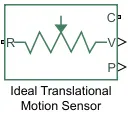
It is a type of sensor which provides the position or velocity input for the system to generate output.
This block measures velocity or displacement in a mechanical translational network. The sensor is ideal since it does not account for inertia, friction, delays, energy consumption, and so on.
The physical signal ports V and P report the velocity and position, respectively, of port R relative to port C. The measured velocity is positive when the velocity at port R is greater than the velocity at port C.
7. Solver Configuration:
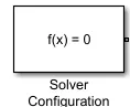
It is a type of block that acts as a complete equation for f(x)=0 where we find the value of x and generates the output which represents the block diagram given above.
It defines solver settings to use for simulation.
8. Electrical and Mechanical References:
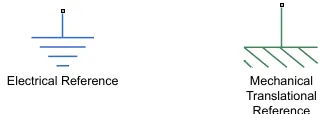
It is the reference block with which the system has a ground source as a base.
9. Scope:
This block will help us to realise the ouput in terms of signals.
It is used to display the plot of simulink results in the form of of waveforms and graphs.
Let us see the complete simulation with all the simscape and simulink block system.
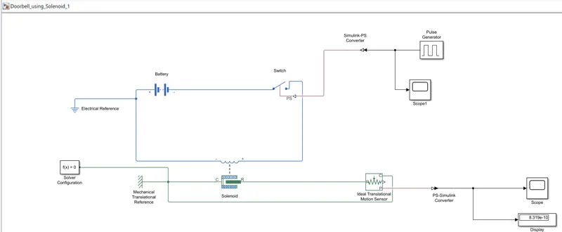
Output:
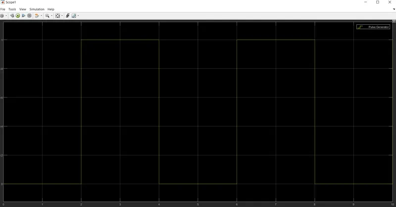
1. For the Pulse Generator the plot realization is:
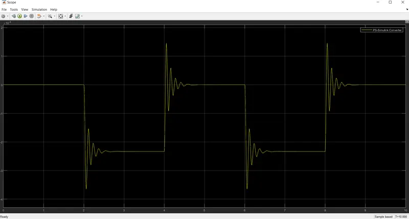
2. For the Position Output of Ideal Translational Motion Sensor:
Answer 2 Explanation:
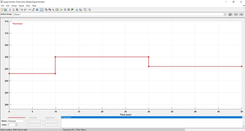
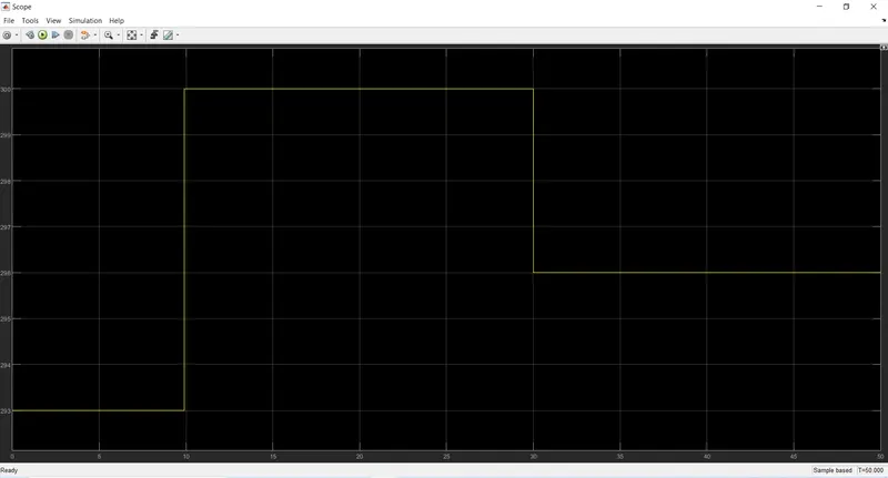
We are given to simulate a thermistor to sense the temperature of a heater according to given condition below
20 °C or 293K from 0 to 10 seconds,
27 °C or 300K from 10 to 30 seconds,
23 °C or 296K from 30 to 50 seconds.
To observe the above details of change in temp with change in time in plot basis we use signal builder block where the input is inserted with these signals.

NOTE:
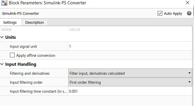
Before we run we need to provide an integrated input in the Simulink-PS converter block to be able to read the systems.
The Simulink and Simscape block design:
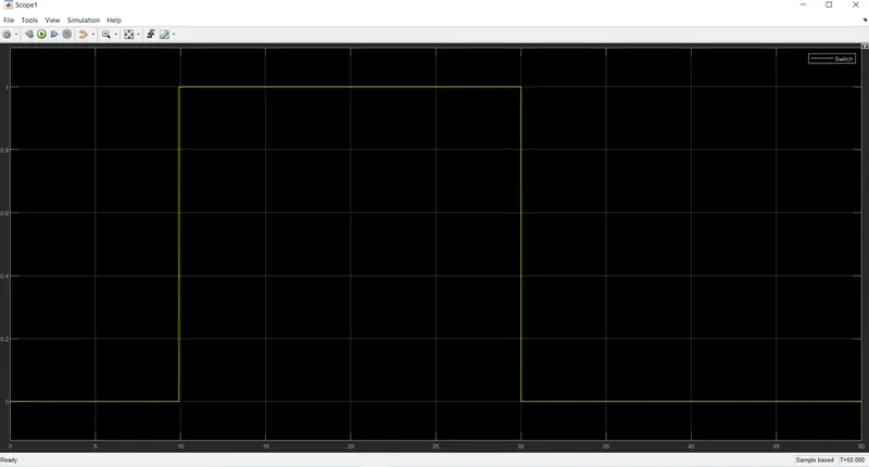
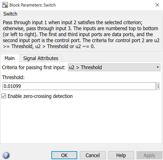
After running for 50 secs we need to provide the display as an input to the switch for ON and OFF conditions.
And thus we get the output of the switch as follows: