Week -2
1. Make a simulink modei of doorbell using a solenoid block with the following detials :
ASW :
> A chime doorbell uses a specilized sort of electromagnet called a solenoid . A solenoid is just an electromagnet where the
coiled wire surrounds a metal piston contains a magnetically conductive metal , so it can be moved backword or forword by the
electromagnatic filed . press the button in the diagram below to see how this works .
>in this desing the solenoid piston consists of an iron core mountted to a non- magnatics metal bar . when there is no power to the electromaget , a spring pushes the piston to the left ,and the iron core extends outside of the wire coil .when you turn the electromagnet on ,by pressing the doorbell button , the iron core is drawn to the magnatic filed , so it slides into the center of the coiled wire.
>as the iron core slides to the right , the end of piston strikes the right-hand tone bar the tone bar vibrates , produsing a particular note .this is the "ding" sound .
CONSTRUCTION :
PS-simulink and simulink -PS convertor :
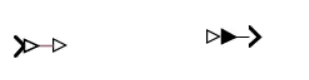
these are basically the converter from physical systems to simulink signals and vice versa.
scope: gives the plot of the output

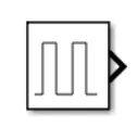
pulse genratator: is an analog input that has amplitude and frequncy with which the inpute is transmitted
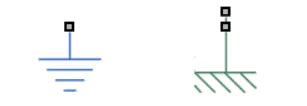
Electrical and mechanical references: is a reference block with which the system has a ground source as a base
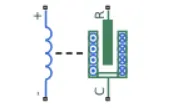
Solenoid : is an electromagnatic device that is represented as a block here.
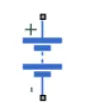
Battery: is a device that has a negetive and a positive terminal for the electric circuit to be complited for an electric flow .
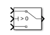
The switch : is a device the completes the electric circuit for a current flow and can be controlled manually or automatically depends on the type of the switch required.
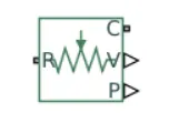
Ideal translated motion sensor : its a type of sensor which provieds the position or velocity input for the sysytem to generate output.
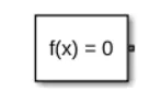
Solver confugration : its a type of block that acts as a complete equation for where f(x)=0 where we find the value of x and generate the ouput which represents the block diagram as an equation .
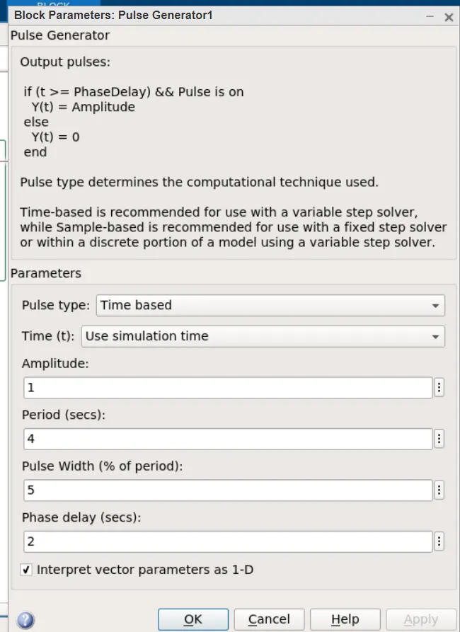
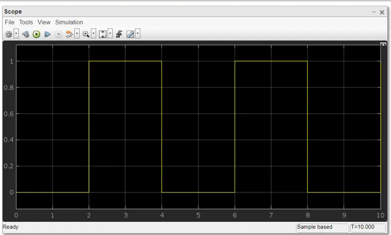
Before we begin the simulation we need to setup and input parameter here in a pulse generator where we delay seconds should be 2 secs withe amplitude 1 and pulse time should be 4 secs to make it in half with 50% pulse width.
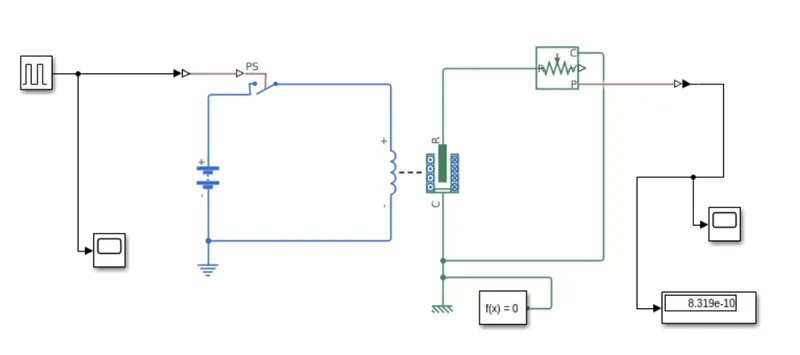
And here is the simulation with all the simscape and simulink block system :
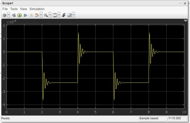
Output :
The input signal of the pulse generator :
Q 2 :
Using a thermistor to sense the temprature of a heater & turn on or off the fan as per givan conditions.
> plus genrater (input) :
in a plus genrater , giving the input value as per the given conditions.
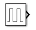
Given inputs:
At point 1 - time 0 sec-
Temperature - 293k,
At point 2 - time 10 sec-
Temperature -293k,
At point 3 - time 10 sec-
Temperature - 300k,
At point 4 - time 30 sec-
Temperature -300k,
At point 5 - time 30 sec-
Temperature -296k,
At point 6 - time 50 sec-
Temperature - 296k,
Controlled temperature source :
The controlled temperature source block represent an ideal source of thermal energy that is powerfull enough to maintain a specified temperature differerance across the source regardless of the heat flow counsumed by the system
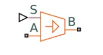
Connection A and B are tharmal consarving part corresponding to the source inlet and oulet , respectivly. port S is the physical singnal port, throgh which the control signal that drives the source is appiled
Thermistor :
A thermistor is the type of resistor whose resistance is dependent on a temprature , more so than in standard resistors. the word is the combination of thermal and resistor .
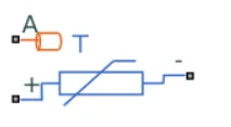
The thermistor block represent an NTC thermistor using the B - parameter equation .
NTC -Negetive temperature co-efficient
Resistor :
The resistor block models a linear resistor , described with the following equation :
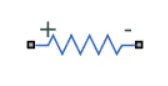
V=I*R
Where
V - voltage,
I - current,
R - resistance
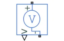
Voltage Sensor :
A voltage sensor block represents an ideal voltage sensor , that is a divice that converts voltage measured between two point of an electrical circuit into a physical signal prapotional to the voltage .
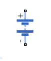
Voltage source :
The voltage source block implements a voltage source with DC ,AC, and noise componants.
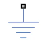
Electrical reference :
The electrical reference block represents
an electrical ground .electrical consarving ports of all the block that are directly connected to the ground must be connected to an electrical refererance bolck .A moduel with electrical elements must contain at least one electrical reference block .
SIMULINK MODEL :
Explanation of model :
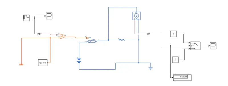
Input are given to the signal builder and connect the temperature controlled source for maintaining the specified temperature difference across the source .the input temperature flow throgh the thermistor.
thermistor is connected with resistor, ensure that thermistor connected with the positive terminal of the resistor and the voltage across the resistor given by V(+)-V(-), And the sign of the current is positive when flowing through the divice from the positive to the negetive terminal this convection ensures that the power absorbed by a resistor is always positive. connect the positive terminal of a voltage source to positive terminal of the thermistal and connect the negative terminal of voltage source to negative terminal of voltage sensor and resistor to get the values from the voltage sensor like a series connection
output terminal of voltage sensor is a connected with switch.using the switch parameter for giving the condition as fan must be ON if the temperature above 25°c OFF otherwise. output is a successfully executed by connecting with a scope as per the given condition
OUTPUT :
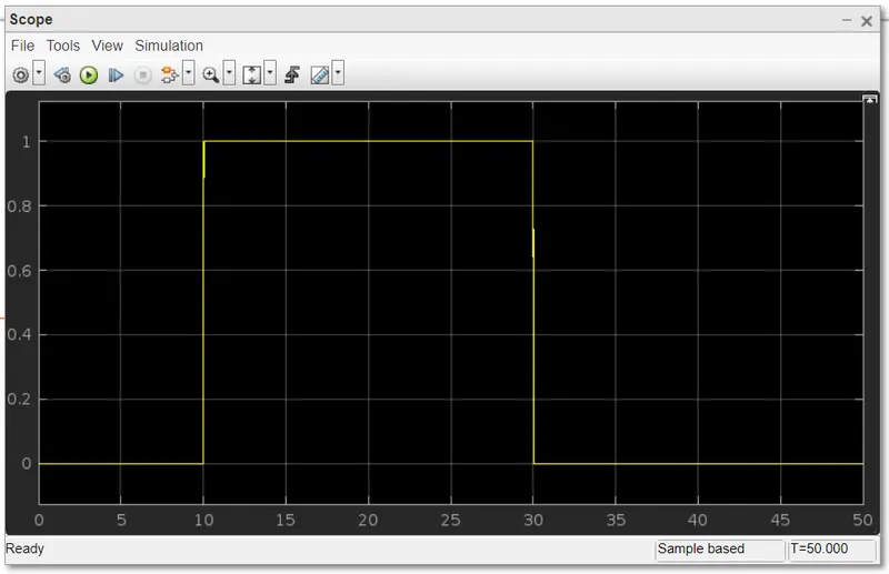
Plot result 1
in the above arrangement,giving input as time peried-2 secs in the puls generator to open and close the switch is closed the switch. whe the switch is closed the solenoid block recives electrical power from the battery and plunger moves frome port R to port C to hit the bell and producing sound
physical movement of the pluger is observed by using ideal translational motion sensor and physical output is converted into similink output model is displayed in the scope. by redusing the spring constant value and incresing the damping value vibration will be reduced
2.
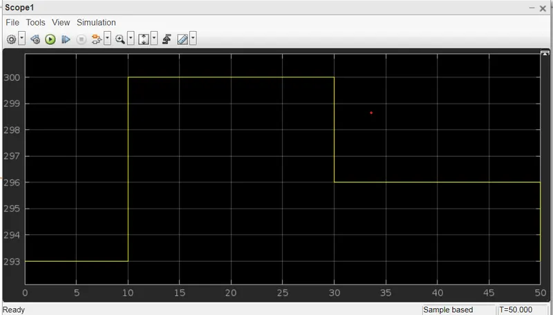
plot result-2
for 0-10 secs fan is in OFF condition, bacause temperatur is 293k which is below 298k. after 10 secs temperature goes to 300k, so fan will turn ON, because temperature exceeds 298k After 30 secs fan will turn OFF because temperature goes to 296k which is belowe 298k.
frome the above result the given condition has been achived and succesfully exwcuted.