Week -2
1) Make a Simulink model of Doorbell using solenoid block
Here first we are going to study the Simulink model of the doorbell using a solenoid block. We need to access the Simulink with the block parameters to run the simulation. First, we need to get to understand the theory behind the Doorbell mechanism.
Theory of Doorbell:
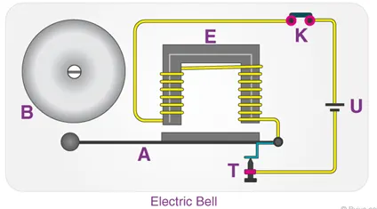
A doorbell uses a specialized sort of electromagnet called a Solenoid. A solenoid is just an electromagnet where the coiled wire surrounds a metal piston. The piston contains magnetically conductive metal, so it can be moved backward or forward by the electromagnetic field. Press the button in the diagram below to see how this works. In this design, the solenoid piston consists of an iron core mounted to a non-magnetic metal bar. When there is no power to the electromagnet, a spring pushes the piston to the left, and the iron core extends outside of the wire coil.
When you turn the electromagnet on (by pressing the doorbell button), the iron core is drawn to the magnetic field, so it slides into the center of the coiled wire. As the iron core slides to the right, the end of the piston strikes the right-hand tone bar. The tone bar vibrates, producing a particular note. This is the ding sound. As long as you hold the doorbell button, the current will flow through the electromagnet and the piston will remain in this position. But when you release the button, the current will stop flowing through the electromagnet and the magnetic field will collapse. The spring snaps the piston back to the left, where it hits the tone bar on the other side. The second tone bar produces the 'dong sound. You can make more elaborate tone sequences by adding more solenoids and tone bars.
Some variations on this design produce a different tone pattern when someone rings the back doorbell than when someone rings the front doorbell. Each doorbell button closes a separate circuit, connected to separate solenoids in the doorbell mechanism. In the simplest design, one of the solenoids hits a bumper instead of the second tone bar. In this way, one doorbell button will trigger a 'ding-dong tone and the other button will trigger only a ding tone. In recent years, more and more people have been installing electronic doorbells in their homes. An electronic doorbell doesn't have any electromagnets or tone bars. Instead, it has an integrated circuit (IC) that registers when the button has been pressed. The IC triggers a digitally recorded song or message.
A lot of electronic doorbells have a wireless control system so the doorbell mechanism doesn't have to be specially wired. Electronic doorbells are growing in popularity, but most homes still use conventional electromagnet doorbells. This classic design may not play elaborate songs or messages, but it is so simple and sturdy that it should be around for a long time to come
The Principle behind Doorbell:
The solenoid is an electromagnet with wire winding and a small metal piston inside it. - When electric current flows through the wire, an electromagnetic field is generated which pulls the metal piston towards it. The metal piston hits the tone bar located on both sides of the arrangement.
Simulink and simscape block setup for the solenoid doorbell:
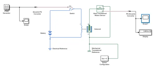
These are the following simscape and Simulink blocks that are going to use in this simulation.
- The pulse generator:
It is an analog input that has amplitude and frequency with which the input is transmitted. It is used to produce square wave pulse at regular intervals. The waveform parameters such as amplitude, pulse width, period and phase delay determines shape of output waveform.
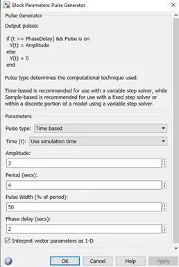
Before we begin the simulation we need to setup an input parameter here in pulse generator where we delay seconds should be 2 secs with amplitude 3 and Pulse time should be 4 secs to make it in half with 50% pulse width.
- Switch:
The Switch is a device the completes the electric circuit for current flow and can be controlled manually or automatically depends on the type of switch required. The switch block used is controlled by external physical signal. If the external signal is greater than the threshold parameter then the switch is closed, otherwise switch is open.
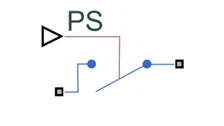
The positive terminal of the switch is connected to switch and the negative terminal is connected to the electrical reference.
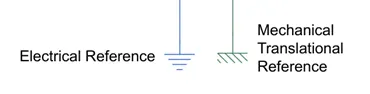
Electrical and Mechanical references:
It is a reference block with which the system has a ground source as a base.
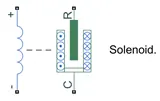
- Solenoid:
The Solenoid block is connected with switch and battery and we will get a complete electrical circuit. The port C is connected with mechanical reference.
- Ideal Translated motion sensor:
It's a type of sensor which provides the position or velocity input for the system to generate output M.
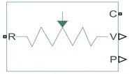
The ideal translational sensor is connected with solenoid block R to observe the movement of the plunger.
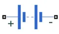
- Battery:
is a device that has a negative and positive terminal for the electric circuit to be completed for an electric flow.
- PS-Simulink converter:
It is used to convert the physical signal to Simulink signal.
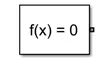
- Solver Configuration:
Each physical network represented by a connected simscape blocks requires solver setting information for simulation. It's a type of block that acts as a complete equation for where f(x) = 0 where we find the value of x and generate the output which represents the block diagram as an equation.
- Scopes:
Gives the plot of the output. Scope is connected with the ideal translational sensor to get the output.
OUTPUT:
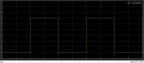
Here we’ve given phase delay of 2 seconds i.e. the switch is ON for two seconds and OFF for next two seconds. The bell will be ringing for period 2 to 4 and off for period 4 to 6 and so on as shown on X axis.
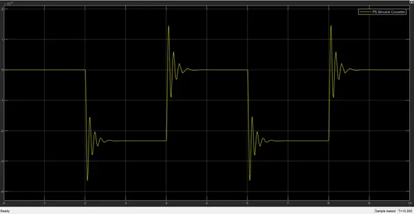
Time period of 2 seconds are given to pulse generator to open and close the switch. When the switch is closed the solenoid block receives electric power from the battery and the plunger move from port R to C to hit the bell and produce sound.
Amplitude is equal to 0 means the switch is closed. We can also see that the clapper strings every 2 seconds. The motion of clapper is as we can see above graph with the help of scope.
CONCLUSION:
We can conclude from the above output results that we have successfully simulated doorbell mechanism operated by solenoid with given conditions as we can saw in above graph.
---------------------------------------------------------------------------------------------------------------------------------------------------------
2) Use a thermistor to sense the temperature of a heater & turn on or turn off the fan
Model:
Theory:
Thermistor:
A thermistor (or thermal resistor) is defined as a type of resistor whose electrical resistance varies with changes in temperature. Although all resistors' resistance will fluctuate slightly with temperature, a thermistor is particularly sensitive to temperature changes. The working principle of a thermistor is that its resistance is dependent on its temperature. We can measure the resistance of a thermistor using an ohmmeter. Thermal resistor is defined as a type of resistor whose electrical resistance varies with changes in temperature. Although all resistor's resistance will fluctuate slightly with temperature, a thermistor is particularly sensitive to temperature changes. Thermistors act as a passive component in a circuit. They are an accurate, cheap, and robust way to measure temperature. While thermistors do not work well in extremely hot or cold temperatures, they are the sensor of choice for many different applications. \
There are two types of thermistors:
- Negative Temperature Coefficient (NTC) Thermistor
- Positive Temperature Coefficient (PTC) Thermistor
In an NTC thermistor, when the temperature increases, resistance decreases. And when temperature decreases, resistance increases. Hence in an NTC thermistor temperature and resistance are inversely proportional. This is the most common type of thermistor.
In a PTC thermistor the reverse relationship between temperature and resistance. When temperature increases, the resistance increases. And when temperature decreases, resistance decreases.
Hence in a PTC thermistor temperature and resistance are inversely proportional. Although PTC thermistors are not as common as NTC thermistors, they are frequently used as a form of circuit protection.
Similar to the function of fuses, PTC thermistors can act as current-limiting devices.
Blocks used:
- Signal Builder: The Signal Builder block allows you to create interchangeable groups of piecewise linear signal sources and use them in a model. You can quickly switch the signal groups into and out of a model to facilitate testing. In the Signal Builder window, create signals and define the output waveforms.
- Simulink-PS Converter: The Simulink-PS Converter block converts the input Simulink signal into a physical signal. Use this block to connect Simulink sources or other Simulink blocks to the inputs of a Simscape physical network Controlled
- Temperature Source: The Controlled Temperature Source block represents an ideal source of thermal energy that is powerful enough to maintain specified temperature difference across the source regardless of the heat flow consumed by the system.
- Thermal Reference: The Thermal Reference block represents a thermal reference point, that is, a point with an absolute zero temperature, with respect to which all the temperatures in the system are determined.
- Thermistor: The Thermistor block represents an NTC thermistor which senses the temperature with respect to time.
- Battery: - The Battery block implements a generic dynamic model that represents the most popular types of rechargeable batteries.
- Voltage Sensor: The Voltage Sensor block represents an ideal voltage sensor, that is, a device that converts voltage measured between two points of an electrical circuit into a physical signal proportional to the voltage.
- Electrical Reference: The Electrical Reference block represents electrical ground. Electrical conserving ports of all the blocks that are directly connected to the ground must be connected to an Electrical Reference block. A model with electrical elements must contain at least one Electrical Reference block.
- Solver Configuration: Each physical network represented by a connected Simscape block diagram requires solver settings information for simulation. The Solver Configuration block specifies the solver parameters that your model needs before you can begin simulation.
- PS-Simulink Convertor: The PS-Simulink Converter block converts a physical signal into a Simulink output signal. Use this block to connect outputs of a Simscape physical network to Simulink scopes or other Simulink blocks.
- Switch: The Switch block passes through the first input or the third input signal based on the value of the second input. The first and third inputs are data input. The second input is control input. Specify the condition under which the block passes the first input by using the Criteria for passing first input and Threshold parameters.
- Constant: The Constant block generates a real or complex constant value signal. Use this block to provide a constant signal input.
- Display: The Display block shows the value of the output data. You can specify the frequency of the display. For numeric output data, you can also specify the format of display.
- Scope: Display signals generated during simulation.in simple word display graph with respect to time.
Explanation Model and Output:
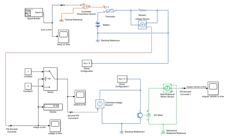
The above model shows the thermistor is used to sense the temperature and switch is used to start and stop the fan.
- Firstly, we add thermistor (NTC) block. The port (T) is connected with a controlled temperature source block. The block one port is connected to thermal reference and another port is connected to converter.
- The temperature difference is set by the physical signal port (S)which is connected to signal builder block with help of Simulink-PS converter. This converter is used because we require physical signal for temperature source input. Our input signal given to signal builder is Simulink signal.
- In signal builder we created an input signal for system.
SCOPE OUTPUTS:
1) Plot of Temperature(oC) vs Time(sec):
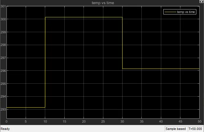
As shown in above graph
for 0 - 10 sec - temperature is 293k (20°C)
for 10 - 30 sec - temperature is 300k (27°C)
for 30 - 50 sec - temperature is 296k (23°C)
2) Plot of switch on/off:
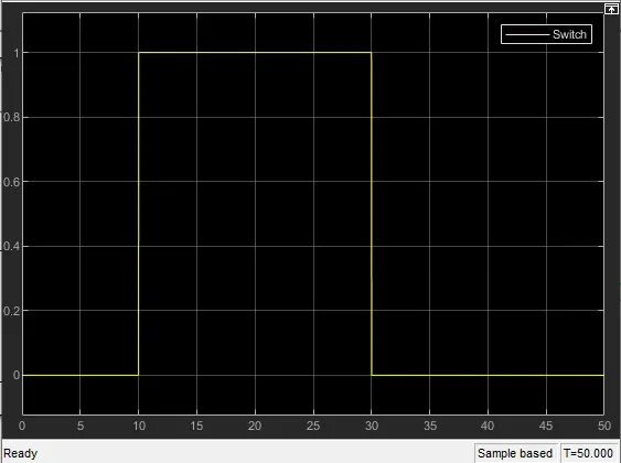
Here x-axis represents time in seconds and y-axis represents amplitude.
Here when the temp is below 25 degreee celcious i.e in 0-10 sec time the switch is OFF as shown value showing zero. In next 10-30 seconds the temperature is 27 degree i.e greater than 25 degree so in this phase the switch will turn ON and so the FAN. Graph showing output value as 1 in this period. and so for the rest 30-50 sec time switch is OFF as temp is below 25.
When the amplitude is 1, then the switch is ON and when the amplitude is 0, then the switch is OFF from the plot it is clear that the switch only be in ON position between 10 and 30 seconds when the temperature is above 25 degree celcius.
3) Plot of voltage vs time:
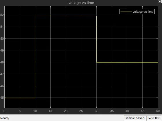
Here x-axis represents time in seconds and y-axis represents voltage.
As the temperature changes the resistance across resistor changes due to thermistor. so the current increases or decreases wrt resistance value. Depends on resistance and current value the threshold value of voltage changes.
In this model we've given threshold as 50 V so when voltage value crosses threshold value i.e goes above 50 then switch will turn ON. As shown in graph for period 10-30 sec. And for 0-10 sec and 30-50 sec voltage value is below 50 so switch will turn OFF.
The voltage value on display is showing 47.97 V because in 30-50 sec temp is 23 degree and according to that temperature resistance cange and so does the voltage value.
4) Plot of angular velocity vs time:
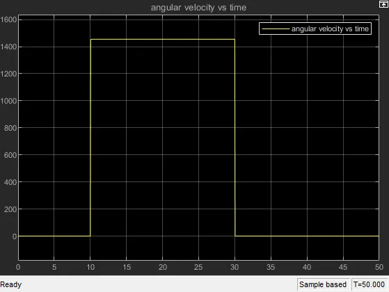
here x-axis represents time in seconds and y-axis represents angular velocity of dc motor.
CONCLUSION:
We have successfully made Simulink model for switching the fan on/off for given condition using thermistor by sensing the temperature of heater.