Week -2
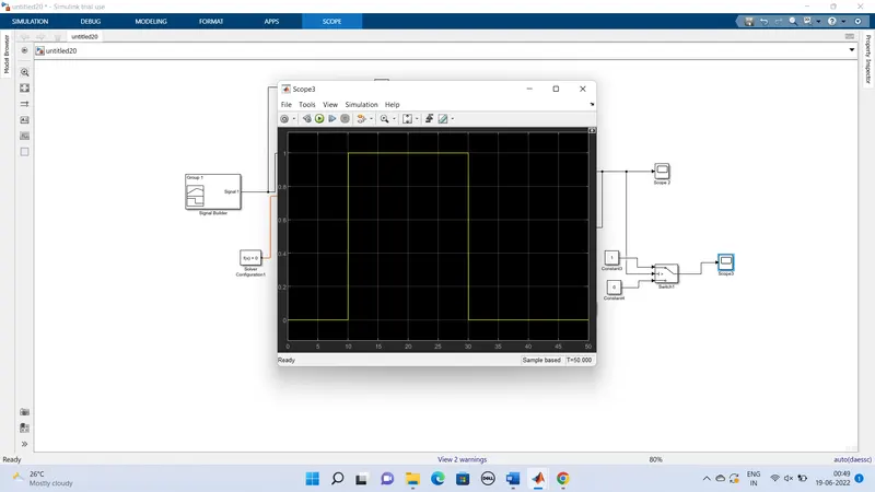
I learnt here what is Simulation configuration and simscape it includes Simulink toolboxes or blockset and toolbox means group of similar models put together e g. R, L, C kept in one toolbox. It is based on application. I also learnt here why simulation configuration needs to be right? because if we are interested to do engine, then what parts takes to make that engine and simulation parameter will decide what situation is of interest: transient steady state or overall and also I learnt important of simulation terminologies.in that video clearly mentioned how does simulation work
Simulation is once model is built, you can real life situation like car racing game i.e we can feel we are inside the car .What is model based design for engineering system i.e it is mathematical models are most suitable for initial experiments. actual system realisation may be costly and time consuming. Some experiments are always better to be done in simulation mode. and also I learnt environments in Simulink and also I understand lookup table [it can be table which will you give data of comparison of function or what value of function or what value of pressure what is going to be output] . 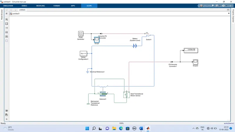
When the switch is pressed the circuit is completed and the electromagnet is activated which makes the hammer strike the bell .the armature is made of iron which attracts the magnet when the circuit is completed.
-Pulse generator is used to simulate the pressing of the bell switch, it has period of 4 sec and duty cycle of 50%, so it will remain open half of wave length and delay of 2 sec.
-Then Simulink -ps converter is used to convert Simulink signal to physical signal.
-This is then connected to a switch controlled by external physical signal with all of its settings left in default, the switch is closed when it receives the signal, otherwise it is open.
-This is connected to battery and then the whole circuit is grounded by an electrical reference
-then the battery and switch were connected to the positive and negative terminals of the left side of the solenoid block, then case terminals was connected to mechanical transitional reference, all the settings of the solenoid were left in default
Then in order to detect the movement of solenoid, an ideal motion translational sensor was used, its reference is connected to the mechanical translational reference, all of its settings were left in default
-Then signal is taken from the port which is measure the displacement and connected to the solver configuration block which is reuired as each and every simscape circuit needs to be attached with the solver configuration block as its specifies solver parameters that the model needs before beginning simulation.
-Then the signal is converted to Simulink signal via ps Simulink converter, and then it is connected to scope to display it.
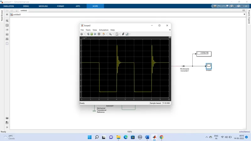
This is a solenoid rated output it follows input signal except for the mass of plunger and spring stiffness and damping, the open fluctuations can be damped it is solenoid rating voltage is the same s battery 2v output.
then second is cooling fan model
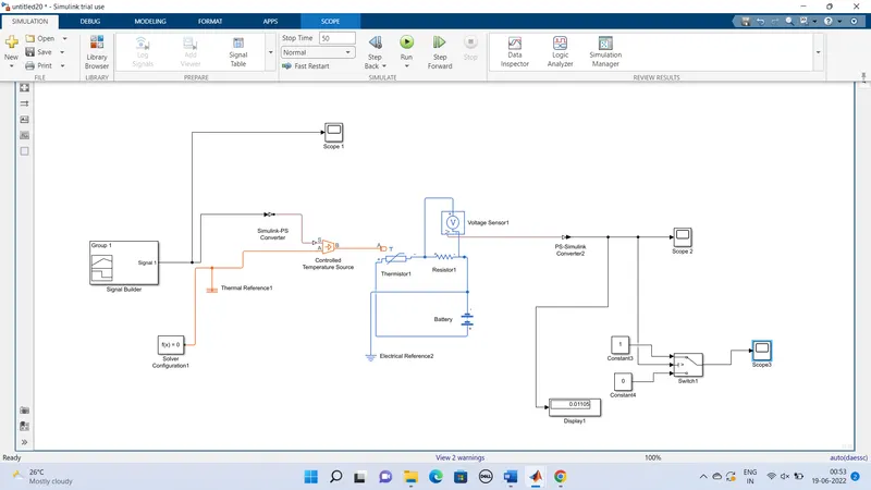
To create simple cooling fan model using thermistor we need signal builder, thermistor, controlled temperature, voltage sensor, battery, resistor, and switch which are basic components of the circuit, we need in the Simulink model.
First to represent the thermistor, thermistor block is taken and placed in the model. Now to represent battery, battery block is taken and positive port of the ‘thermistor block’.
Now to represent resistor, ‘resistor block’ is taken from the library browser and its positive port is connected to negative port of the ‘thermistor block’. The negative port of ‘Resistor block’ is connected to the negative port of the ‘Battery block’. Now an ‘Electrical Reference block’ is connected near the negative terminal of the ‘battery block’ which represents the earthing of the real time circuit.
Now to represent voltmeter ‘Voltage Sensor block’ is connected parallel to the ‘Resistor block’, because to measure to voltage cross component, voltmeter should be; always connected parallel to that component.
Thus, we have completed our simple circuit model, but we need some physical unities to as signal for thermistor to work.
In this case we need the fan to get ON and OFF at different temperature. So, to provide temperature, we have used ‘controlled Temperature Source Block’ which only gives specified temperature s output even though het flow is more.
Now to give different temperature at this ‘Controlled Temperature Source block’ we need to send temperature signals. To send these signal we have used ‘Signal Builder Block’ which allows use to send any type of signals as input
We have to double click on the ‘Signal Builder Block’ to set the signal according to our reuirement.
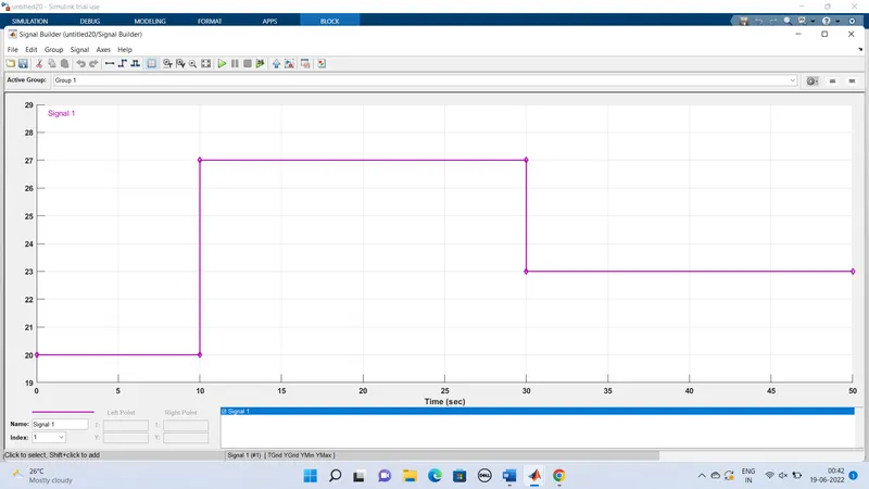
When we open the ‘Signal Builder block’. as this dialogue box opens, first we have to click on the ‘signal’ at the top and then select ‘New’ ten select ‘Custom’ option. Now it will ask to give values of y-axis and x-axis. Since we know that at which times, we need which temperature s mentioned in the string, we can give those values in an array in this box and then the above figure signals re generated.
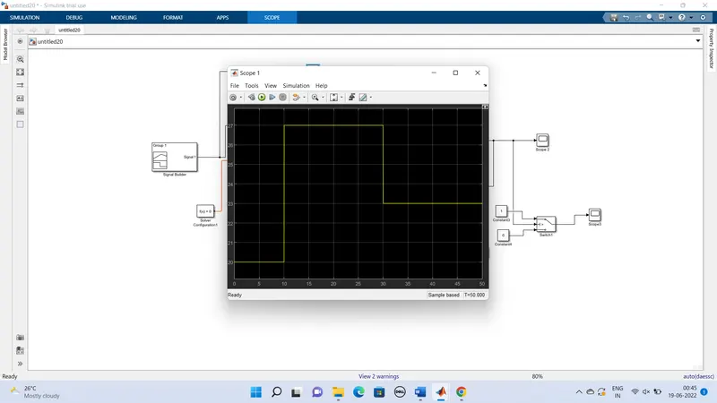
We can see that how different temperature are given at different time. So, thus we have how different temperature are given at different time. So, thus we have created our signals and before connecting it to the ‘controlled Temperature Source block’ we have to convert these signals into physical value. So, to do this we have used ‘Simulink-PS Converter block’.
So now port B of ‘controlled Temperature Source block’ is connected to port ‘a’ of the ‘Thermistor block’ and port ‘’of ‘Controlled Temperature Source block’ is connected to the ‘Thermal reference block’. In ‘Controlled Temperature Source block’ positive temperature different cases the temperature at port ‘’ to be greater than the temperature t port ‘’.
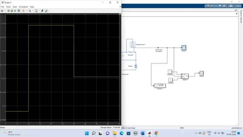
Now output of the ‘Voltage Sensor block’ is connected to ‘Display block’ first, and before connecting to the ‘Display block’ ‘PS- Simulink Converter’ is used to convert sensor block physical values to Simulink values.
Now when we run the simulation and double click on ‘Display block’ and we will get the voltage at 25 degree C, then fan should ON otherwise OFF.
This above logic used to ON and OFF the fan. To do this we have used ‘Switch block’ that routes the signals according to the conditions provided.
The centre port of ‘Switch block’ is connected to output of ‘PS-Simulink’ converter which gives the voltage values. The top port of the ‘Switch block’ is connected to constant block of value and bottom port of the ‘Switch block’ is connected to another ‘Constant block’ of value 0.
The centre port of Switch block is condition input which means that when the value from, ‘voltage
Sensor block’ is more than the threshold value in the ‘switch block’ then it will pass the value 1 which we have specified in the top port of the ‘switch block’. If the voltage from ‘voltage senor block’ is less than the threshold value in the ‘switch block’. He it acts like transistor in real time circuit.
To set the threshold value of ‘switch block’, we have to double click on the ‘switch block’ and then we can change the value of threshold. since we want switch to be on only when temperature is 300k so the threshold is given s 1.10555e-02. So when voltage gets more than 1.10555e-02 the switch will give value 1 s output which means fan will be ON and when voltage gets less than 1.10555e-02 the switch will give value 0 s output which means fan will be off.
Now the output of the ‘switch block’ is connected to another port to get the results.
SCOPE 1
SCOPE 2
SCOPE 3