Week -2
- Doorbell simulation model
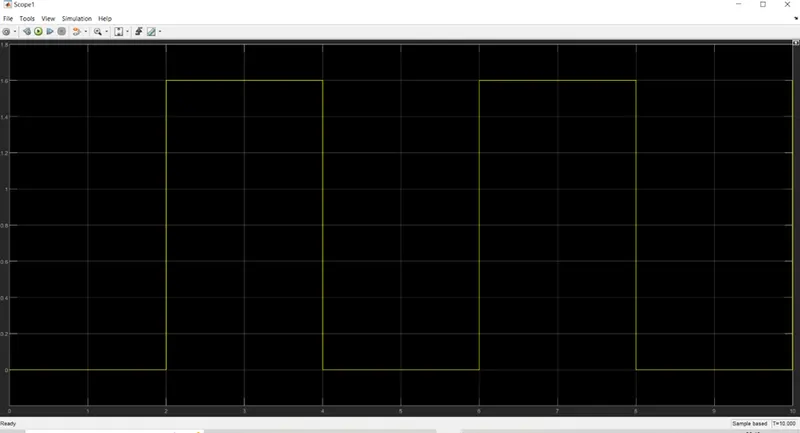
- Pulse generator:- Pulse with amplitude :- 1.6 ; period- 4 sec & pulse width - 50%
- Single-Pole Double-Throw (SPDT): The block represents a Single-Pole Double-Throw (SPDT) switch controlled by an external control signal vT. If vT is greater than the threshold, then the switch is closed, otherwise the switch is open.
If a non-zero threshold width is defined, then the switch conductance varies smoothly between off-state and on-state values as vT varies between threshold and threshold plus threshold width. The threshold width must be zero to enable switched linear solver optimizations.
Threshold = 1.5 set
- Voltage source :- This block models a voltage source with DC, AC and noise components. The output voltage is defined by v = v_dc + v_ac * sin(2*pi*f*t + phi) + v_n where v_dc is the DC amplitude, v_ac is the peak AC amplitude, f is the frequency, phi is the phase shift and v_n is the noise voltage. DC voltage = 52 V
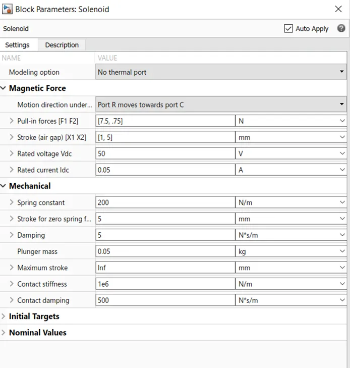
- Solenoid :- This block implements the electrical and mechanical characteristics of a solenoid. Parameterization is in terms of two points [X1,F1] and [X2,F2] on its force-stroke curve for a 100 percent duty cycle at Rated voltage Vdc and Rated current Idc where X2>X1>0 are stroke values and F1>F2>0 are corresponding forces. The plunger fully in (i.e. air gap closed) corresponds to X=0, and pull-in force is assumed to decrease quadratically with the magnitude of X. To ensure the force remains finite, the following condition should hold: X2/X1>sqrt(F1/F2).
The plunger Maximum stroke is implemented as a hard stop, the dynamics of which are set by the Contact stiffness and Contact damping parameters. The same parameters are used to model the contact dynamics when the plunger pulls fully in. The Spring constant parameter is used to implement a spring force that pulls the plunger out, and can be set to zero.
Damping = 5 N/m/sec
- Ideal Translational Motion Sensor:- This block measures velocity or displacement in a mechanical translational network. The sensor is ideal since it does not account for inertia, friction, delays, energy consumption, and so on.
The physical signal ports V and P report the velocity and position, respectively, of port R relative to port C. The measured velocity is positive when the velocity at port R is greater than the velocity at port C.
- Input Pulse generator:-
- OUTPUT POSITION :-
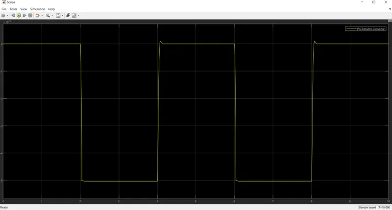
Bell is operated from time scale of 2sec to 4 sec i.e. for a period of 2sec as the SPDT switch is connected to Voltage source and the Solenoid operates . The position is varying in the output position scope from 0 to -5 ( inward movement)
- Result: - Bell operates for 2 sec and stops ; again operates for 2 sec and so on.
The model is working as per requirement.
- Thermistor Controlled Fan
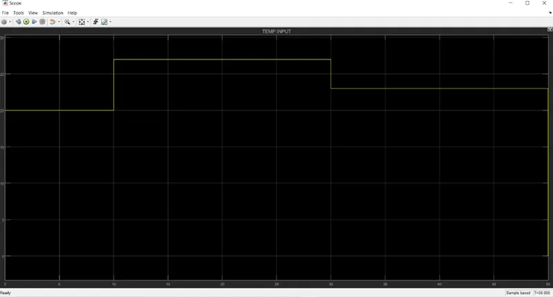
- Pulse Generator :- Three Pulse generator with summation is used for generating the required Temperature Signal
- Controlled Temperature Source:- This block represents an ideal energy source in a thermal network that can maintain a controlled temperature difference regardless of the heat flow rate. The temperature difference is set by the physical signal port S. A positive temperature difference causes the temperature at port B to be greater than the temperature at port A.
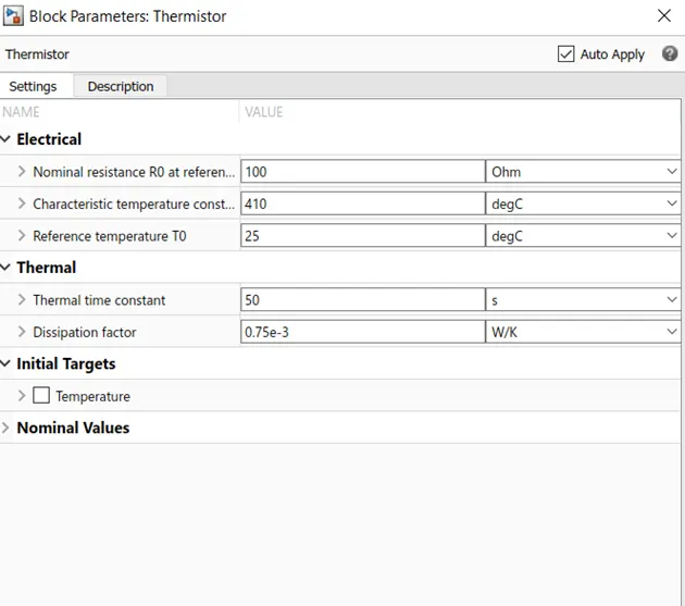
- Thermistor:- This block represents an NTC thermistor using the B-parameter equation. The resistance at temperature T is given by R(T) = R0*exp(B*(1/T-1/T0)) where R0 is the Nominal resistance at the reference temperature T0, and B is the Characteristic temperature constant. The temperature T of the thermistor is governed by the equation m*c*dT/dt = Q where Q is the net heat flow into port A, m is the mass and c is the lumped specific heat capacity. The thermal mass m*c is calculated from the Thermal time constant t_c and the Dissipation factor K_d using the equation m*c = K_d*t_c.
- Voltage Source:- This block models a voltage source with DC, AC and noise components. The output voltage is defined by v = v_dc + v_ac * sin(2*pi*f*t + phi) + v_n where v_dc is the DC amplitude, v_ac is the peak AC amplitude, f is the frequency, phi is the phase shift and v_n is the noise voltage.
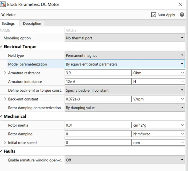
- DC Motor :- This block represents the electrical and torque characteristics of a DC motor. The block assumes that no electromagnetic energy is lost, and hence the back-emf and torque constants have the same numerical value when in SI units. Motor parameters can either be specified directly, or derived from no-load speed and stall torque. If no information is available on armature inductance, this parameter can be set to some small non-zero value.
When a positive current flows from the electrical + to - ports, a positive torque acts from the mechanical C to R ports. Motor torque direction can be changed by altering the sign of the back-emf or torque constants.
- Ideal Rotational Motion Sensor:- This block measures angular velocity or angle in a mechanical rotational network. The sensor is ideal since it does not account for inertia, friction, delays, energy consumption, and so on.
The physical signal ports W and A report the angular velocity and angle, respectively, of port R relative to port C. The measured angular velocity is positive when the angular velocity at port R is greater than the angular velocity at port C.
- OUTPUT :-
- Result:-
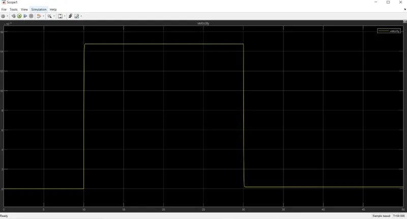
- Temperature is 20 deg for first 10 sec and observe there is No rotation of Fan.
- Temperature if 27 deg for next 20 sec ; as the temperature is more than 25 deg only the fan is operating & Rotational output is measured in the Scope.
- Temperature is 23 deg for next 20 sec and observe there is No rotation of Fan.
The model is working as per requirement