Week -2
The Make A Slimulink Model of DoorBell using solenoid block with following dedails:
AIM:
to make a simulink model of DOORBELL using solenoid.
CONDITION:
The arrangement, when the switch is closed the elecromagnet receive electrical power from the battery and pulls the metal arm to hit the bell producing sound by createing a situation where the switch is closed for 2 secs and then released.
DOORBELL BASIC CIRCIUT DIAGRAM GIVEN BELOW
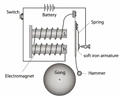
WE HAVE USING THE FOLLOWING THE BLOCK MODELS:-
1.puls Generator:
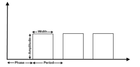
THe pulse Generator block generates square wave pulses at regular intervals.the block wavefrom parametters, Amplitude,pulse width,period,and phase delay, determine the square output wavefrom.the following diagram shows how each parameters affectst the wavefrom.
2.BATTERY:
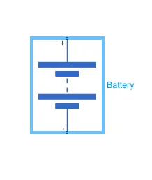
The block models a battery.if you select infinite for the battery charge capacitty parameter,the block models the bettery as a series internal resistance and a constant voltage source.
3.SWITCH:
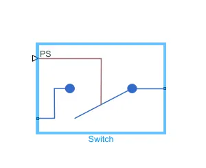
The block repersants a switch controlled by an external physical signal.
4.solenoid block:
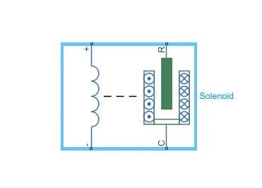
This block implement the electrical and mechanical characteristics of a solenoid.
5.ideal Translation Motion sensor Block
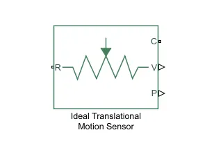
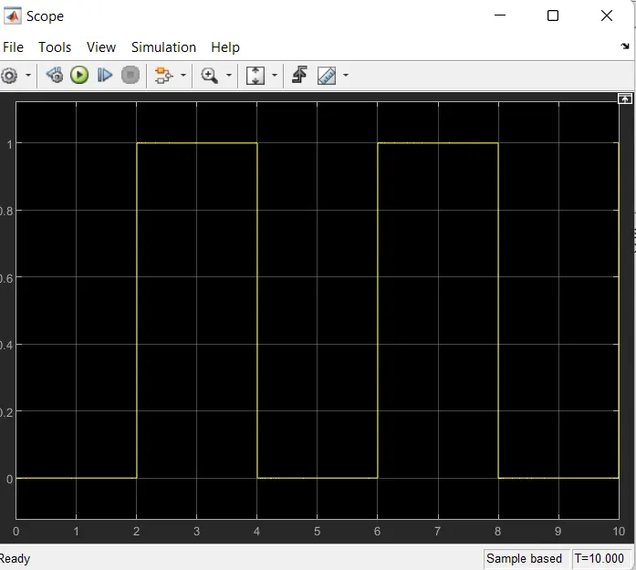
This block measures velocity or displacement in a mechanical transulation network.connection R and C are mechanical translational conserving ports that connect the block to the nodes whose motion is being monitroed.connections V and p are physical signal output ports for velocity and position,respectively.
This block positive direction is from prot R to port c.This means that velocity is measured as v=vR-vC,where Vc are the absolute velocities at port rR and C,Respectively.
portc is connected with mechcnical translational Reference.
6.SCOPE:-

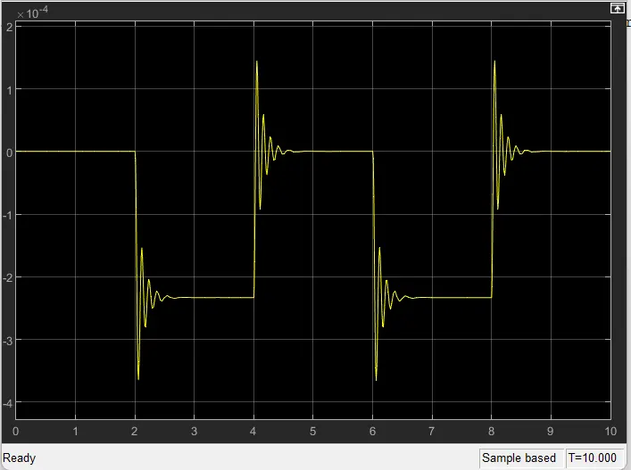
Scope is connected with Ideal Translation motion sensor to get the output the real-time scope block accquires data in chunk of size number of samples from the real time application that is executing on the target computer.
7.Ps-Simulink Converter
The ps-simulink converter block converts a physical signal into a simulink output signal.use this block to connect outputs of a physical network diagram to simulink scope or other simulink blocks.
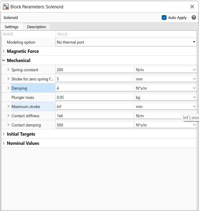
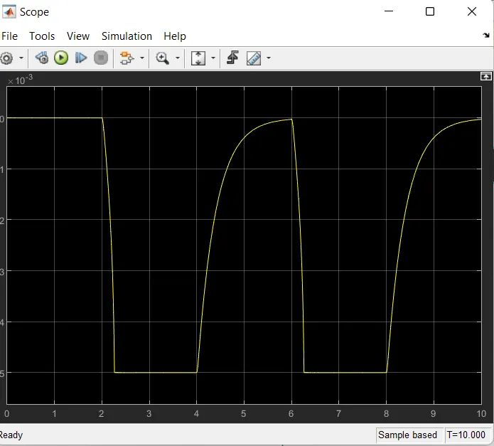
8.simulink-ps convertor:

This block convert simulink signals into physical for opertional use in Model.
9.Elecrical Reference Block:
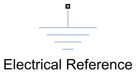
The Electrical Reference block represents on electrical ground.Electrical conserving ports of all that are directly connected to ground must be connected to an Electrical reference block.
10.Mechanical Transulation Reference Block:

This block represents a mechanical translation reference point,that is,a frame or a ground.use it to connect mechanical translational ports that are rigidly affixed to the frame(ground)
11.solver configuration:
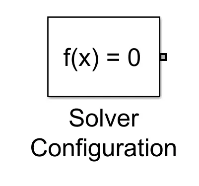
define solver settings to use for simulation.each physical network represented by a connected simscape block diagram requires solver settings information for simulation
SIMULINK MODEL:
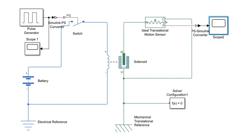
EXPLANATION:-
1.Now first a"solenoid block" is taken to represent a solenoid in the model ,thento represend battery we have taken battery block from the library browser.
2.Then this solenoid block &battery block are connected to each other via positive and negative terminals
3.A "switch block"is placed between "solenoid block"and "battery block"and connected the both blocks.
4.Now for switch to operate we need to provide physical signal through"ps port in the "switch block".The provided physical signal should be greater than the threshold of the switch,for switch being close,or else it will be open
5.Now this whole battery switch and solenoid path is connnected to an "Electric Reference Block"which represents earthing of thi circuit.This "Electric Reference Block"should be connected to the negativeterminal of "Battery Block
6.Then in the solenoid block "R"and"C"are two variable which represent Plunger and Fixed point respectively.
7.Now the solenoid block "R"connected to "R" of Ideal translation motion sensor Block which sensethe position of plunger in the solenoid Block and gives the output.
8.Now in the "IEDAL TRANSLATION MOTION SENSOR BLOCK"the output are givein as "v" and "p" whitch repersent the velocity and position of the plunger.Since we are only interested in knowing the change in position of the plunger,so we need only result of "P"output.
9.And the "solver configuration"we now connect the "Mchanical Translational reference".
10.Now "c"in the in the "Ideal translation motion sensor block"is machanicaltranslation conserving port,which means that the mechanical process starts from"R"and end "c" and again is starts "R"and the cycle goes on.
11.So "c"in the "ideal translation motion sensor block"is connected to "Mechanical translation reference"whitch represents a fix point where it is rigidly clamped in real time.
12.similarly"c"of the solenoid block is also connected to the some Machanical Translation Reference"as fixed point for solenoid .
13.since we position of the plunger as output from "ideal Translation sensor block "we have connected port "p"to "A" PS-simulink convertor where the physical value from port"P"are connnected into simulink value,and then this PS-simulink convertor"is connected to "scope block"which will generate a graph for change in position of plunger from port"P"of ideal translation motion sensor block'.
14.Now to provide a physical signal for operating the switch ,we used a"pluse generator block"whitch generates a continuous square pulse.
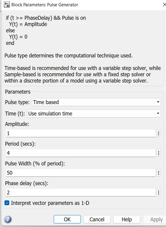
15.From the above figuare we can observe we have given period value of "4"pulse width as "50",phase delay as "2"and amplitude by defult is "1"have not changeit.This means that initially the pulse will be Zerro ,since we have given phase Delay of "2"so till 2sec the pulse will be Zero and at the end of "2" sec the pulse will start rising from zero to 1,since we have given amplitude as "1"and then now the pulse width will be half of period,so for the next 2seconds the pulse will be amplitude"1"only,then it will again come down to zero at 4th seconds and then it will be zero.so after these 4 seconds period again the pulse will be generated and thus cycle continues
16.To this "pulse generator"a"scope block is connected to see how the pulse is generated.
17.The above figure is obtanined by running the simulink model and double clicking the "scope block".this figure show how the pluse is generated and in this figure the x-axis respresents the "Ampilitude"".As mentioned in point no16,the pulse has started from 2sec and ending at 6sec which is nothing but a time period of 2 sec.
18.This represents that when amplitude is ,1 the switch will be colsed and current will start flowing and when it is zero the switch will open and current stop flowing.Since our objective is only to see change in position of plunger when switch is closed for 2 sec, so we have the ampliitude as 1 for 2 sec in the pulse generator by making the pulse width half of the period on the inputs fir "pulse generator block".
19.As the mention above ,the port "P"of ideal Translation motion sensor Block"is connected to another "scope2 Block".
20.Now RUN the model and Double cilk on the "scope2" which is connected to "ideal Translation Motion sensor Block"to get the result.
RESULT:-
21.We will get the above graph as the result when we double cilk on "scope 2 block".here x-axis Represent the "Time"and y-axis resperent position of plunger in mm.
22.From the above figure we can abserve that the initial position of the plunger is at "5mm" as from pulse generator block ,a pluse generated at 2 ,so in the position of the plunger is also changing at time 2seconds and time till which the pulse Ampitude "1"till that time pluger is also at the same positioin after the change from initial position.
23. Again,as the Amplitude of the pluse become zero the plunger return to the Original position back again and as the pulse cycle goes on,pluger is also at same position afterthe change ffrom initial position.
24.we can also observe that when there changein position of plunger,there is same wave form at the start of change in position. this is due recoil of spring each time when the plunger is movieng.so to reduce this in the "solenoid block " we can reduce spring constant value and increase the damping coeffient.This will reduce the Waves that are being formed and we will get a smooth graph.
25.The above figure is a smoother graph then previous one .This was done by changing the value of the spring constant and damping coefficient in the "solenoid Block".
CONCLUSION:
* The physical movement of the plunger of solenoid was observed when switch is closed for 2 seconds.
* Simulink particularly helps to improve the performance by Analyzing it on plot and charging the suiteable configuration,as in above case of solenoid operated bell spring constant" And "Damping"was varied as shown above
--------------------------------------------------------------------------------------------------------------------------------------------------------------------------------------------------------------------------------------------
2.USE A THERMISTOR TO SENCE THE TEMPERATURE OF A HEATER &TURN ON OR TURN OFF THE FAN PER THE BELOW
AIM:-
create a simulink model of thermistor sence the temperature of a heater &turn on or turn off the fan
ondition:
Temperature source:20°C from 0 to 10 seconds,27°C from 10 to 30 seconds,23°C from 30 to 50 seconds.
Fan condition: ON if the temperature above 25°C,OFF otherwise.
Blocks used in model:
SINGAL BUILDER: -
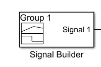
The Signal Builder block allows you to create interchangeable groups of piecewise linear signal sources and use them in a model. You can quickly switch the signal groups into and out of a model to facilitate testing. In the Signal Builder window, create signals and define the output waveforms.
Controlled Temperature Source:
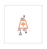
The Controlled Temperature Source block represents an ideal source of thermal energy that is powerful enough to maintain specified temperature difference across the source regardless of the heat flow consumed by the system.
THERMISTOR:
The Thermistor block represents an NTC thermistor using the B-parameter equation.
RESISTOR:
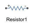
The Resistor block models a linear resistor, described with the following equation V=I·R
VOLTAGE SENSOR:
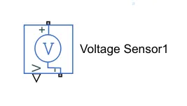
The Voltage Sensor block represents an ideal voltage sensor, that is, a device that converts voltage measured between two points of an electrical circuit into a physical signal proportional to the voltage.
Battery:
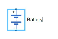
The Battery block represents a simple battery model.The instrumented modeling options have an extra physical signal port that outputs the internal state of charge.
Swithch:
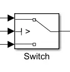
The Switch block passes through the first input or the third input signal based on the value of the second input. The first and third inputs are data input. The second input is a control input. Specify the condition under which the block passes the first input by using the Criteria for passing first input and Threshold paramet.
Electrical reference:
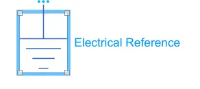
The Electrical Reference block represents an electrical ground. Electrical conserving ports of all the blocks that are directly connected to ground must be connected to an Electrical Reference block. A model with electrical elements must contain at least one Electrical Reference block.
Thermal Reference:
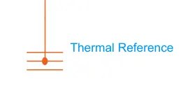
The Thermal Reference block represents a thermal reference point, that is, a point with an absolute zero temperature, with respect to which all the temperatures in the system are determined.
PS-simulink converter:
The PS-Simulink Converter block converts a physical signal into a Simulink output signal.
simulink -ps converter:
The Simulink-PS Converter block converts the input Simulink signal into a physical signal.
Constant:
The Constant block generates a real or complex constant value signal. Use this block to provide a constant signal input.
Solver Configuratoin:
Each physical network represented by a connected Simscape block diagram requires solver settings information for simulation.
SCOPE:
The scope Used to view grapihic design result.
Model Explanation:
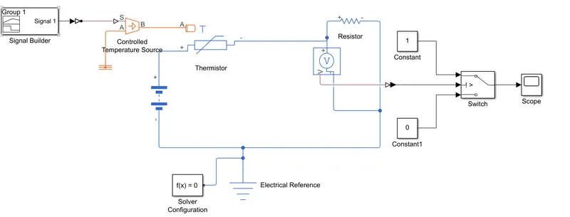
A signal builder is given as input to the thermistor through a controlled temperature source.The signal builder block givin valve of below.
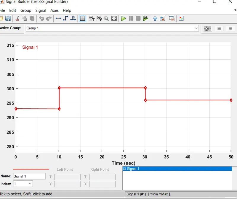
The condition of the temperature source is defined inside the above window. The whole simulation time was taken 50sec.
Battery and a resistor connected the temperature circuit.A voltage sensor was given accross this resister to measure the voltage change during different temperature inputs.The resistor can be set to any value ,but it should not be changed once the thersold voltage is found .The thersold temperature was given as 25 degree celsius and the corresponding voltage over the resistor was found out,through switch connected the voltage sener.The switch both are connected to constant valve and as switch is output connect to the scope.
result:
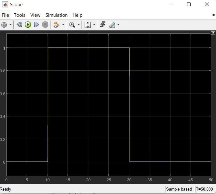
ON CONDITION- 10 to 30 seconds from300K
OFF CONDITION- 0 TO 10 Seconds From 293k and 30 to 50 from296k
-------------------------------------------------------------------------------------------------------------------------------------------------------------------------------------------------------------------------------