Week -2
1) Door Bell Simulink Model:
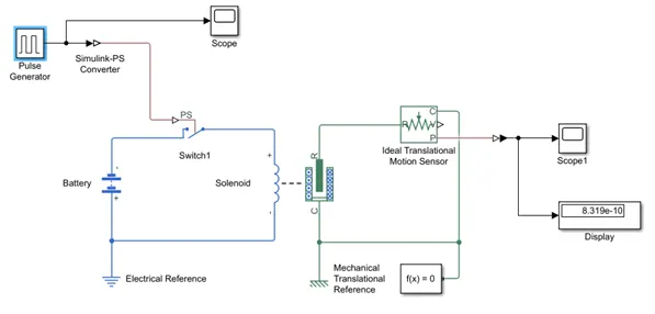
The above simulink model of is a doorbell by solenoid block
- The Pulse generator is used to create pulse square wave at regular intervals.
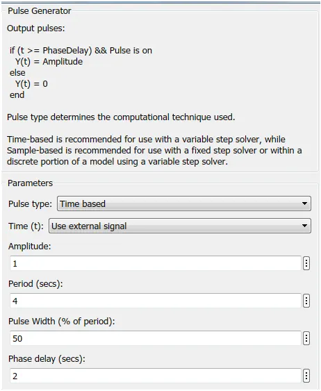
The Input of Pulse Signal Generator is shown in graph
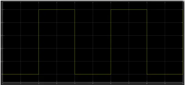
- The switch block is used to controlled by external Physical signal. Switch is closed when the external signal is more than the threshold voltage otherwise switch is open always.
- In the positive side of the battery is connected to solenoid and negative side is connected to switch so we will get complete complete Electrical Circuit. The port C is connected to Mechanical reference.
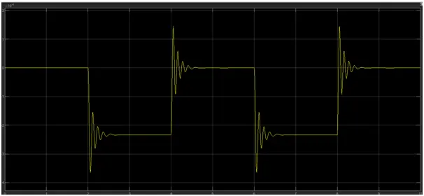
- The ideal translation sensor is connected with solenoid block R to observe movement of the plunger & Scope is connected to translation sensor to see the output.
- PS- simulink converter is used to convert the physical signal into Simulink signal.
Output of Signal after pressing door bell:
2) Use a thermistor to sense the temperature of a heater & turn on or turn off the fan as per the below conditions:
Temperature source: 20 °C from 0 to 10 seconds, 27 °C from 10 to 30 seconds, 23 °C from 30 to 50 seconds Fan conditions: ON if the temperature above 25 °C, OFF otherwise.
Thermistor :
- Thermistors are temperature-dependent resistors, changing resistance with changes in temperature. They are very sensitive and react to very small changes in temperature. They are best used when a specific temperature needs to be maintained, and when monitoring temperatures within 50°C of ambient.
- Thermistor acts as a passive component in circuit. They are very accurate, cheap and robust way to measure temperature. While thermistor do not work well in extremely hot and cold condition.
- Following is the simulink block assembly thermistor based heater with the below conditions.
1st Condition: 0 to 10 seconds temperature 293K
2nd Condition: 10 to 30 seconds temperature 300K
3rd Condition: 30 to 50 seconds temperature 296K
Insert above mentioned signals in signal Builder Block and below you can see the details in plot basis
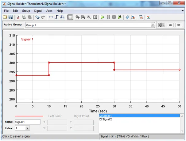
- Control temperature source represents an ideal source of temperature energy that can maintain a controlled temperature difference regardless of the heat flow rate. The temperature difference is set by physical signal in port S.A positive difference causes at port B to be greater than the temperature a port A.
- Voltage sensor is used to convert the voltage measured between two points into physical signal.
Output:
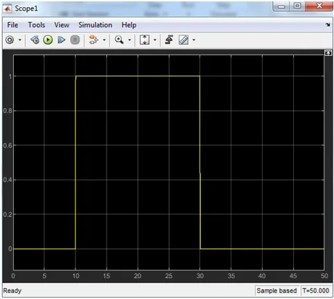
For 0 to 10sec fan is in off condition because temperature is 293k which below the threshold 298k. After 10s temperature goes to 300K then the switch will be ON condition as temperature more than 298k. After 30sec fan will be off as temperature comes down to 295k which is below threshold temperature.