Week -2
- Q1-Make a Simulink model of Doorbell using solenoid block with the following details:
In the above arrangement, when the switch is closed the electromagnet receives electrical power from the battery and pulls the metal arm to hit the bell producing sound.
Create a situation where the switch is closed for 2 seconds and then released. Observe the physical movement of the plunger.
Solution:-
When electric current passes through a wire it behaves like magnet this is the magnetic effect of electric current. current carring insulated coil wrapped around the piece of iron called as Electromagnet.
The power of electromagnet is increased by increasing number of turns of coil. it also can be increased by increasing the flow of current. A electromagnet can be turned off by stopping the electric current.
Let's unnderstand how electromagnet used in doorbell.
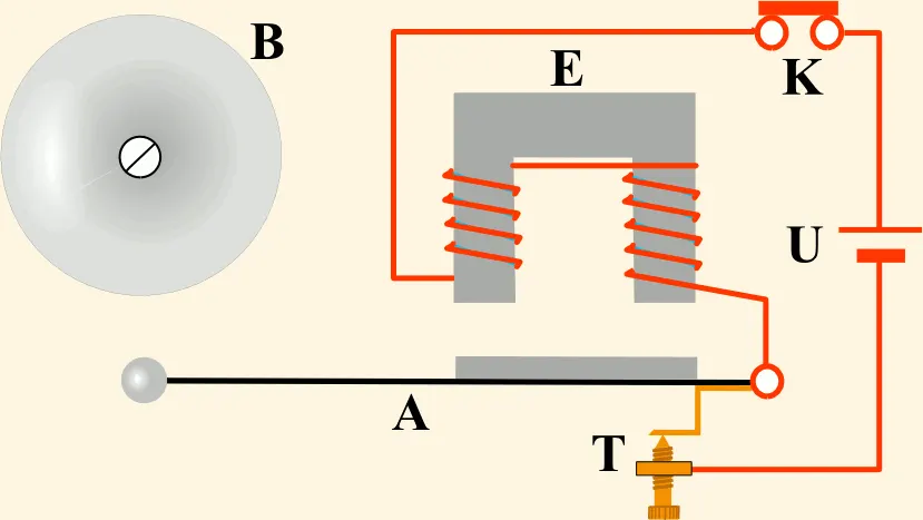
Diagram consist of coil of wire wound on iron peice bent to form 'U' shape like a horseshoe magnet.
spring loaded arm made up of iron strip is kept close to the electromagnet. this arm has a hammer attached to the at one end called as clapper. There is a contact screw near the clapper.
Now when the switch on the circuit, clapper is in contact with a screw, so the circuit is complete and current flow throgh the coil due to the current flow coil becomes a electromagnet and pulls and clapper towards itself.
the clapper strikes on a gong bell and produce a sound. But when a electromagnet pulls a clapper and produce a sound clapper losses its connection with Screw and circuit is broken then current throgh the coil will stop and coil will not
remain electromagnet. clapper spring away from the bell and comes to its original position and again comes with contact screw and complete circuit again. this process is repeated again and again.
Simulation Model :-
Blocks used in this Model :-
- Mechanical translational reference :- This block represents a mechanical translational reference point, that is, a frame or a ground. Use it to connect mechanical translational ports that are rigidly affixed to the frame (ground).
-
Ideal Translational motion sensor :- This block measures velocity or displacement in a mechanical translational network. The sensor is ideal since it does not account for inertia, friction, delays, energy consumption.
-
Solenoid :- This block implements the electrical and mechanical characteristics of a solenoid. Parameterization is in terms of two points [X1,F1] and [X2,F2] on its force-stroke curve for a 100 percent duty cycle at Rated voltage Vdc and Rated current Idc where X2>X1>0 are stroke values and F1>F2>0 are corresponding forces. The plunger fully in (i.e. air gap closed) corresponds to X=0, and pull-in force is assumed to decrease quadratically with the magnitude of X. To ensure the force remains finite, the following condition should hold: X2/X1>sqrt(F1/F2).
-
Battery :- This block models a battery. If you select Infinite for the Battery charge capacity parameter, the block models the battery as a series internal resistance and a constant voltage source. If you select Finite for the Battery charge capacity parameter, the block models the battery as a series internal resistance plus a charge-dependent voltage source defined by:
V = Vnom*SOC/(1-beta*(1-SOC)
-
Switch :- The block represents a switch controlled by an external physical signal. If the external physical signal PS is greater than the threshold, then the switch is closed, otherwise the switch is open
- Pulse generator :- The Pulse Generator block generates square wave pulses at regular intervals. The block waveform parameters, Amplitude, Pulse Width, Period, and Phase delay, determine the shape of the output waveform. The following diagram shows how each parameter affects the waveform.
-
Solver Configuration :- Each physical network represented by a connected Simscape™ block diagram requires solver settings information for simulation. The Solver Configuration block specifies the solver parameters that your model needs before you can begin simulation.
Each topologically distinct Simscape block diagram requires exactly one Solver Configuration block to be connected to it.
- Electrical Reference :- The Electrical Reference block represents an electrical ground. Electrical conserving ports of all the blocks that are directly connected to ground must be connected to an Electrical Reference block. A model with electrical elements must contain at least one Electrical Reference block
- Scope :- Display signals generated during simulation.
Model Explanation :-
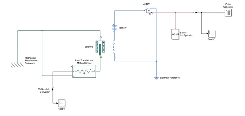
Pulse generators output is given to simulink converter to convert physical signal into respective simulink signal and given to the switch.
The switch block has three terminals one terminal is connected to the battery's positive End and another connected to the Electrical reference point.
Solenoid block is connected to switch and battery terminal to complete the circuit.
R port of the solenoid is connected to the motion sensor to sense the movement of the solenoid.
C port is connected to the mechanical referance.
Scope is connected to the Motion sensor to seen the output.
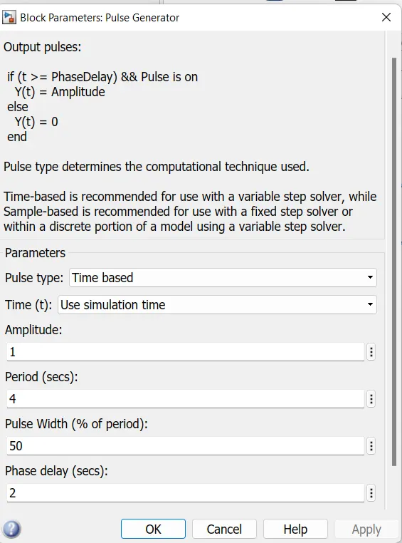
- Inputs given to the pulse generator
Output :-
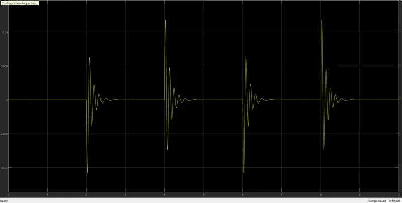
For 0-2 Sec the output is Null and from 2 to 4 sec its gives oscillations
As we can clearly seen there is some movement and deflection in Spring.
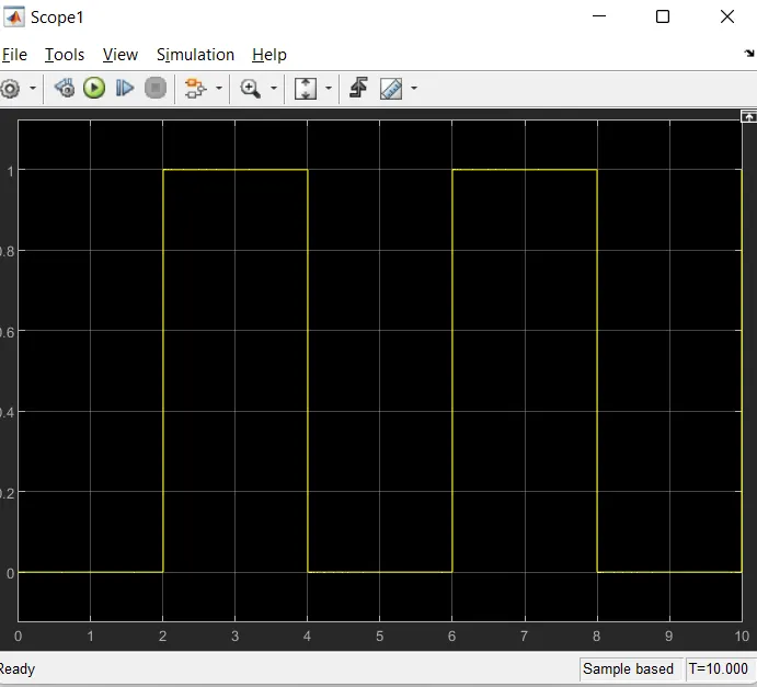
2. Use a thermistor to sense the temperature of a heater & turn on or turn off the fan as per the below conditions:
Temperature source: 20 °C from 0 to 10 seconds, 27 °C from 10 to 30 seconds, 23 °C from 30 to 50 seconds
Fan conditions: ON if the temperature above 25 °C, OFF otherwise
Solution :-
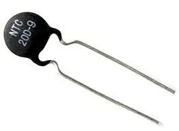
- "Thermistor"
Thermistor is a temperature sensing resistor. Its resistance varies with temperature. Thermistor have come from the words thermal and resistors. Thermistor is made up of semiconductors and some metallic oxides such as nickel , manganese, Iron, copper, etc. They can sense even small change in temperature.
There are mainly two types of thermistor
- Positive temperature coefficient (PTC)
- Negative temperature coefficient (NTC)
Simulink Model :-
Model Explanation:-
Simulink Blocks required for challenge
- Signal Builder:- Signal Builder to generate the signal according to the input condition given
- PS-Simulink converter :- Converts Simulink signals to the respective physical signal
-
Controlled temperature source (CTS) :- Provide a temperature physical output based on the condition given to port S
-
Thermal reference:- Thermal reference block provides the required initial conditions to the connected thermal block for the solve
-
Thermistor :- Thermistor black which shows us the NTC thermistor relation between temperature and resistance.
-
Battery :- Battery is a storage device that provides the required voltage based on the parameter given. We can use DC voltage source too
-
Resistor :- Resistor which provides the opposing nature of current in a circuit.
-
Voltage sensor :- This is used to measure the voltage or potential difference across any electrical component and it should connect in parallel only.
-
Electrical Reference :- These domain-specific electrical reference blocks will provide the required initial conditions to the connectedthermal block for the salver
-
Solver Configuration: The Solver Configuration block specifies the solver parameters that your model needs before you can beginsimulation and this is mandatory for all simscape designs
-
Constant:- Provides a constant output value
-
Switch :- This block is used from the library Simulink / Signal Routing where it has three inputs nomely Portl, Port2, and Port3 Port2 is acontrol input where the signal given to port2 is satisfied with the condition and threshold of the switch block then it passes Portlasoutput and if it is not satisfied then it will pass Port3 as output
- Scope :- This is an output block that shows the signal with respective time in an X-axis
Explanation:-
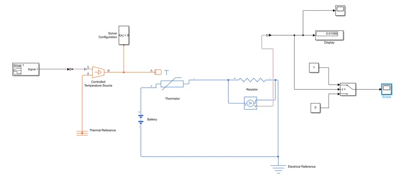
In above circuit NTC thermistor is used. It has namely three terminals from that two are electrical ports which are '+' and '-' terminals which will be connected to battery source.
third terminal is Thermal port H which provides a resistance tempreture this port A has been connected to the controlled tempreture source block. this will provide the required tempreture as per given signal.
Signal builder block used as signal provider P-S converter is used to convert simulink signal into physical signal.
Registor is connected in series with Thermistor. Voltage sensor is connected in parallel to register.
The output of the voltage sensor is given to the switch and display.
Switch has three inputs namely Portl, Port2, and Port3. Port2 is a control input. threshold of the switch block then it passes Portlas output and if it is not satisfied then it will pass Port3 as output.
Thermistor takes input tempreture in "Kelvin" so convert Signal of signal builder into Kelvin
To convert Celcious into kelvin just add 273 in celcious Ex.- 20 C + 273 = 293 Kelvin
So as per the question 20C , 27C and 23C tempreture is given
convert given Tempreture into Kelvin
20C = 293K
27C = 300k
23C = 296K
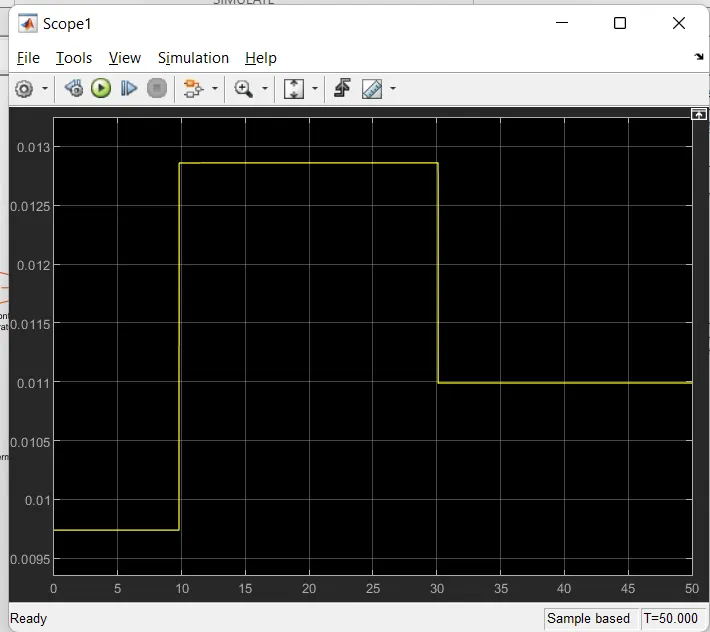
Output :-
298K is Threeshold value to turn on fan.
When ever tempreture is below 298k Fan is in OFF condition
And when tempreture is 298K or above it the Fan in ON condition.
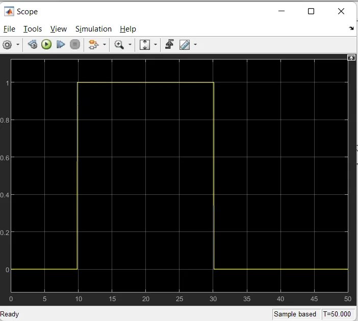
For 0 to 10 Sec Tempreture is 293K so Fan in OFF condition.
For 10 to 30 Sec Tempreture is 300K so Fan in ON condition.
for 30 to 50 Sec tempreture is 296K so Fan in OFF condition.