Week -2
AIM: -
- To create the stimulation of the bell.
- With the help of a thermistor to sense the temperature of a heater & turn on or turn off the fan as per the below conditions.
Temperature source 20○C from 0 to 10 seconds, 27○C from 10 to 30 seconds, 23○C from 30 to 50 seconds fan conditions: ON if the temperature above 25○Coff otherwise
1). TO CREATE WORKING STIMULATION OF THE BELL: -
CONSTRUCTION OF A BELL: -
One end of armature winding is connected to terminal T1 and the other to a spring, which is mounted on a soft iron strip. A rod is attached to the armature and the free end of the rod carries a small hammer, which strikes a bell. A very light spring is attached to a screw, which is joined to a T2.
WORKING PROCESS OF A BELL: -
The electric circuit is completed through a battery and push switch button connected to the terminal T1 and T2 . When the push button is pressed the electric circuit is completed and the armature is attracted towards the electromagnet as a result, the small
Spring gets detached from the screw due to which electric circuit is broken and the electromagnet is demagnetized. Hence, the attraction disappears and the armature is brought back by the spring to its original position. Contact of the spring with the screw is now remade, which completes the electric circuit. The action reappears over and over again consequently. The armature vibrates and the hammer attached to it strikes the gong and the bell rings and sound is produced.
SIMULINK BLOCK
- . PS-SIMULINK AND SIMULINK-PS CONVERTER: These are basically the converter from physical systems to Simulink signals and vice versa.
- . SCOPE: Gives the plot of the output.
- . PULSE GENERATOR: This is an analog input that has amplitude and frequency with which the input is transmitted.
- . ELECTRICAL AND MECHANICAL REFERENCES: This is a reference block with the system that has a ground source as a base.
- . SOLENOID: This is an electromagnetic device that is represented as a block here.
- . BATTERY: This device has a negative and positive terminal for the electric circuit to be completed for an electric flow.
- . THE SWITCH: This device completes the electric circuit for current flow and can be controlled manually or automatically depending on the type of switch required.
- . IDEAL TRANSLATED MOTION SENSOR: This is a type of sensor which provides our velocity input for the system to generate output.
- . SOLVER CONFIGURATION: This is a type of block that acts as a complete equation for where f(x) = 0 where we find the value of x and generate the output which represents the block diagram as an equation.
MODEL EXPLAINATION
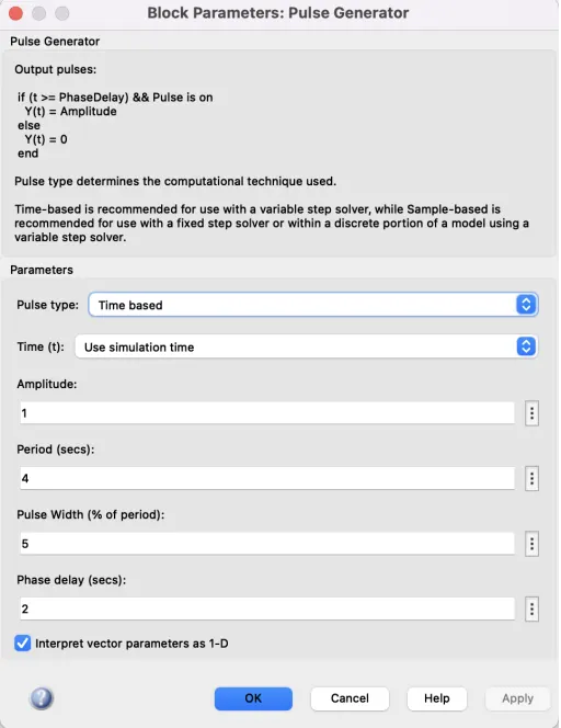
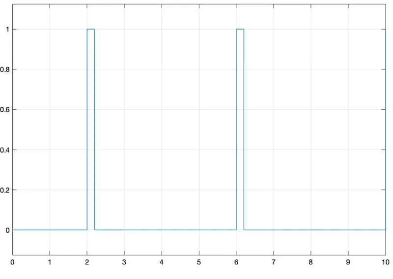
The pulse generator is used to give the signal input where Amplitude=1, Period=4secs,
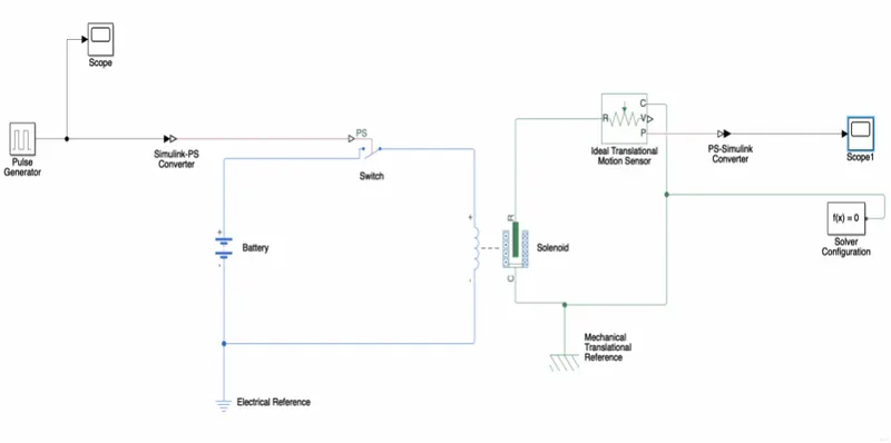
pulse width =5% and the phase delay = 2secs. The input signal is converted into physical form with the use of SIMULINK PS CONVERTER and further sent to the SWITCH of the electrical circuit. The electrical circuit consists of a SOLENOID, a BATTERY, and a SWITCH. One end of the SOLENOID is connected to the BATTERY and its other end is connected to the SWITCH. An ELECTRICAL REFERENCE is provided in the electrical circuit. The mechanical part of the SOLENOID is connected to an IDEAL MOTION SENSOR and MECHANICAL TRANSLATIONAL REFERENCE. Thus, the P port of the sensor makes a connection with the PS SIMULINK CONVERTER to provide the output in signal form. Further the converter is connected with SCOPE to DISPLAY the output signal. A SOLVER CONFIGURATION is connected to an electrical circuit to solve all parameters before the beginning of the simulation.
PULSE GENERATOR
Before we begin the simulation, we need to set up an input parameter here in pulse generator where we delay seconds should be 2secs with amplitude 1 and pulse time should be 4 secs to make it half with 50% pulse width.
CIRCUIT BLOCK DIAGRAM: -
THE INPUT SIGNAL OF THE PULSE GENERATOR
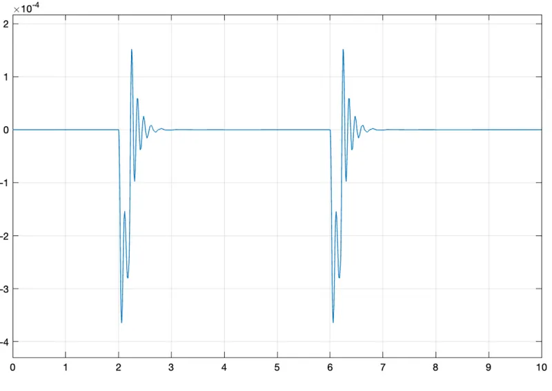
OUTPUT
The motion of the plunger was simulated and recorded and plotted in scope.
- To CREATE A SIMULINK BLOCK USING THERMISTOR AND TO SENSE THE GIVEN TEMPERATURE LIMITS: -
THERMISTOR: - A thermistor is a type of resistor whose resistance is strongly dependent on temperature, more so than in standard resistors. The word thermistor is a combination of thermal and resistor. It is made of metallic oxides pressed into a bead, disk, or cylindrical shape and then encapsulated with an impermeable material such as epoxy or glass. Two types of thermistors are negative temperature coefficient and positive temperature coefficient. With a negative thermistor when the temperature increases, resistance decreases. Similarly, when the temperature decreases resistance increases. This type of thermistor is used the most. A Positive thermistor works a little differently. When temperature increases, the resistance increases, and when temperature decreases. This type of thermistor is generally used as a fuse. Typically, a thermistor achieves high precision within a limited temperature range of about 50○C around the target temperature. This range is dependent on the base resistance.
SIMULINK BLOCK
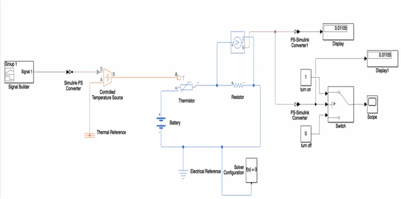
This figure shows the representation of the thermistor connection which senses the temperature of the heater and passes the signal to a switch where a threshold limit is already set. If the temperature is above or equal to the threshold limit, then it gives I as output which is switch on. If the temperature is below the threshold limit, then it will give 0 as output which means switch off. The input signal is generated with the help of a signal builder block. This signal is created according to the conditions given in this challenge.
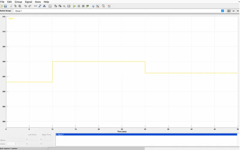
The temperature source is set to the following conditions:
The formula for the conversion is 1○C=273.15k
- For 0 to 10 secs the temperature should be (20○C)15k.
- For 10 to 30 secs the temperature should be(27○C)15k.
- For 30 to 50 secs the temperature should be (23○C)15k.
STEPS TO CREATE THE MODEL
- The signal is created in SIGNAL BUILDER and further passes to SIMULINK-PS CONVERTER to convert the input signal into the physical signal.
- This physical signal is connected to a block CONTROLLED TEMPERATURE SOURCE. This block is connected to the THERMISTOR and a THERMAL REFERENCE block.
- The THERMISTOR is a part of an electric circuit where a battery, a voltage sensor, a resistor connected parallel to the voltage sensor and electrical reference is connected to make a complete circuit. A SOLVER CONFIGURATION is connected to that electrical circuit to solve all parameters before the beginning of the simulation.
- The VOLTAGE SENSOR senses the temperature in the form of voltage and sends the data to its port V.
- From this port we get our output and send it to two different PS-SIMULINK CONVERTERS.
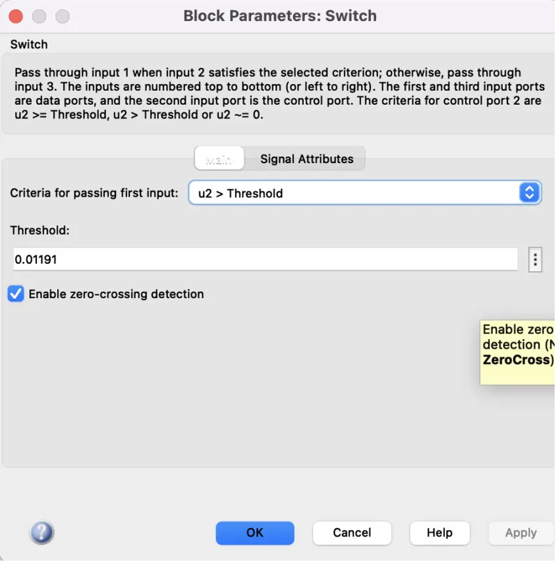
- From CONVERTER-1 the signal is sent to the threshold SWITCH. In the switch the threshold limit is set to 0.01191. if the temperature is below the threshold limit, then it gives I as output which is SWITCH ON. If the temperature is below the threshold limit, then it will give 0 as output which means SWITCH OFF. The input signal is generated with the help of a scope SIGNAL BUILDER block.
- The switch is connected to the SCOPE where we can see our output plot.
- From CONVERTER-2 it converts the physical signal into a Simulink signal and sends the voltage data from the voltage sensor to display. This display gives us the threshold value of voltage. The value is set in the switch.
Signal builder inputs.
Switch block parameters
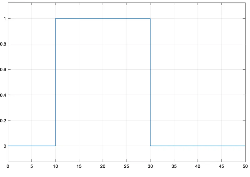
OUTPUT:
It is seen that the value of signal is 0 from 0-10 sec because in this time the
temperature was 20○C which is below 25○C means it will switch off the fan. After that the signal value gives I as output from 10 - 30 sec because in this time the temperature was 27○C which is above 25○C means it will switch on the fan. The value of the signal is again goes to 0 from 30-50 sec because in this time the temperature was 23○C which is below 25○C it will switch off the fan.
Now it is clear that our model is correct and fulfils all the input conditions.
REFERENCES: -
https://skill-lync.com/knowledgebase/thermistor-challenge
https://en.wikipedia.org/wiki/Thermistor
https://in.mathworks.com/help/simulink/slref/signalbuilder.html