Week -2
1.
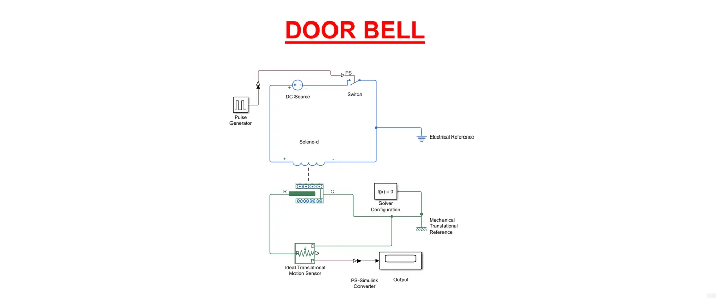
Description:
The above is a Simulink model is of a Door Bell using a Solenoid block. In the above arrangement, when the switch is closed the electromagnet receives electrical power from the battery and pulls the metal arm to hit the bell producing sound. The change in position of the metal arm/plunger is indicated by the change in position of 'R' in the solenoid which has been measured using an Ideal Translational Motion Sensor Block and has been displayed using the Scope Block.
The condition applied was that the switch be closed for two seconds and then released for which a pulse generator block is used. Since the simulation running time is 10 seconds, this phenomenon is repeated every two seconds, i.e, five times.
Observation :
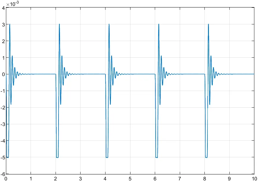
It is to be noted here that the plunger(metal arm) gets displaced to its maximum value of 5 units with every electrical input that it receives every two seconds(because of the pulse generator) from the DC source which then gets dampened by the spring present in the solenoid and gradually reaches 0. The damping effect on the plunger is dependent on the characteristics of the spring of the solenoid. As such, every two seconds the bell will ring with maximum itensity which will then reduce gradually to 0 in about 1.2 seconds.
The simulation file is attached for reference.
2.
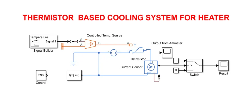
In the above model, a signal builder is used to generate the varying stemperatures with time and then the signal is passed to through the controlled temperature source to the thermistor. Being an NTC thermistor, the resistance of the thermistor drops with an increase in temperature. This drop in resistance causes an increase in the amount of current (Ohm's Law)passing through the circuit which is measured using the ammeter/current sensor.
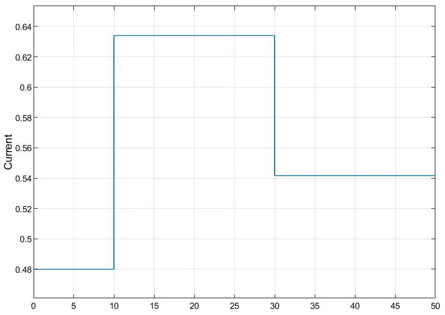
The above plot shows the variation in the current with respect to the change in temperatures.
As per the conditions, the fan needs to switch on for temperatures more than 25 degrees C and turn off for temperatures lower than that. Therefore to calculate the threshold current, the control temperature of 25 degrees C or 298 K is used as the input which gives the corresponding current of 0.587 A passing through the Ammeter.
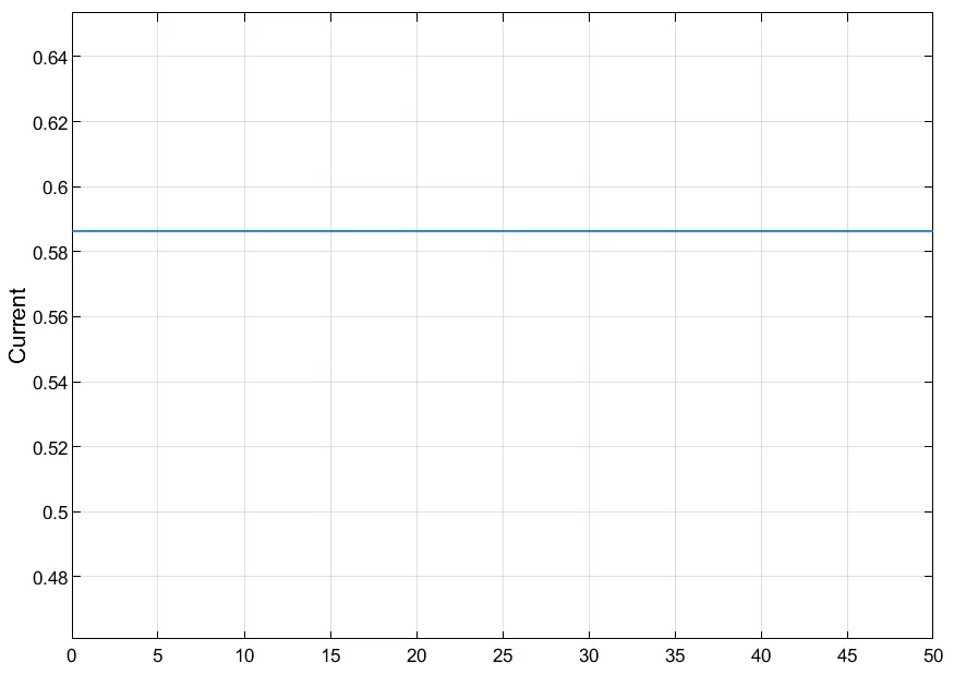
The above plot shows the value of current (~0.587 A)to be used as threshold for 25 degrees C.
A switch is used to provide output signal 1 in case of currents higher than 0.587A and an output signal of 0 for currents lower than 0.587 A.
In the final results, it is clear to see that the output is 1 (fan is on) from time 10 to 30 seconds when the temperature is 27 degrees C, and is 0(fan off) for 0 to 10 seconds and from 30 to 50 seconds where the temperatures are 20 degrees C and 23 degrees C respectively.
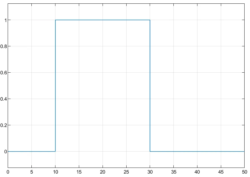
The final result, showing that the fan is on (output signal 1) from 10 to 30 seconds when the temperature is >25 degrees C and, that the fan is off (output signal 0) when the temperature is <25 degrees.