Week -2
1)
Aim: To create a Simulink model of the doorbell using the Solenoid.
Objective: Creating the Doorbell using the block in Simulink and learning the basic arm motion of the doorbell.
Blocks or Components:
1) Scope:
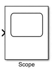
To get output we need this Scope block which will represent the signals.
2) Solenoid:
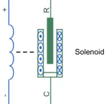
This block which is having both the electrical and mechanical part. The electrical input is converter into the mechanical output.
3) Pulse Generator:
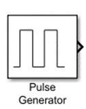
The Pulse Generator block generates square wave pulses at regular intervals. The block is having two type output representation Time Based Mode and Sample Based Mode.
4) Battery:
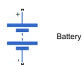
This block help supply the electricity to the connected solenoid.
5) Simulink PS Converter:
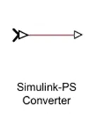
This block which help to connect between the Simulink to Simscape.
6) PS Simulink Converter:
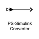
This block which help to connect between the Simscape to Simulink.
7) SPST Switch:
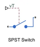
The SPST (Single pole Single Throw) This block will come role when the input is given then the switch becomes close.
8) Ideal Translational Motion Sensor:
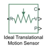
This block is used to detect weather there is any linear motion in the solenoid block during the simulation. This block measures velocity or displacement in a mechanical translational network. The sensor is ideal since it does not account for inertia, friction, delays, energy consumption.
9) Electrical Reference:
This block which is help given the electrical ground.
10) Solver Configuration:
The Solver Configuration block specifies the solver parameters that your model needs before you can begin simulation.
11) Mechanical Reference:
This is used to give ground for the mechanical component.
Model Explanation:
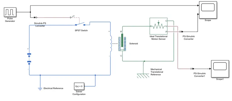
Step 1) Created the Simulink new file.
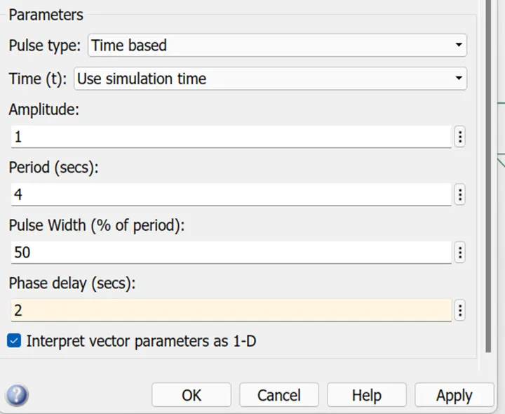
Step 2) Take the pulse generator this block is used to give input signal like amplitude, pulse width, period and phase delay to determine the output.
Step 3) Pulse Generator is connect to the Simulink PS Converter, converter output is connected to the SPST Switch.
Step 4) The SPST Switch is connected to battery and Solenoid block. The SPST Switch terminal connected to battery positive and solenoid positive.
Step 5) The Solenoid block which is contain electrical and mechanical parts. The Electrical part which is in blue colour and Mechanical part which is in the green colour.
Step 6) The Electrical Reference and Solver Configuration are also connected because the electrical reference which is used as the ground and solver configuration which is used as the specify the solver parameter.
Step 7) The Mechanical part of solenoid is connected to ideal translation motion sensor. And Mechanical Reference is used for ground purposed.
Step 8) The scope is used to see output graph which is connected to the ideal translation motion sensor.
Step 9) Now the pulse generator input will be Amplitude = 1, Period = 4, Pulse Width = 50, Phase delay = 2.
Step 10) Now the output will be ready.
Input:
Model of the Door bell
Pulse Generator Input
Output:
 \
\
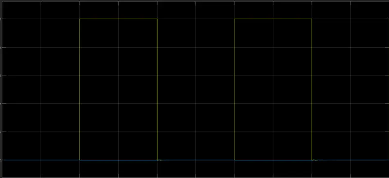
We get above graph by giving the input to the pulse generator with respected to the amplitude, pulse width, period and pulse delay.
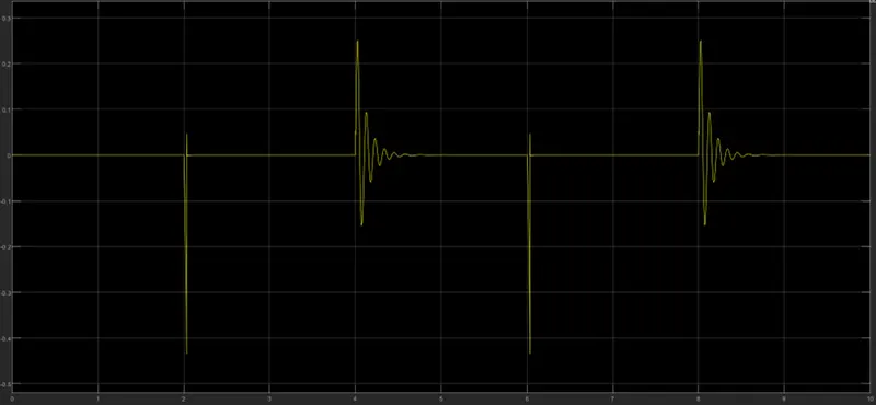
In the above graph we can see that the switch is closed for 2 seconds and after that switch is will open. But the Amplitude will remain equal to zero that means the switch will be closed. But after next 2 sec, the plunger will be engage and there will be movement of the plunger. As we known that Stop time will be given for the 10 sec so that up to 10 sec this process will be continued.
Conclusion:
We can conclude that by see above graph result that we complete simulation of the DoorBell with the respected condition.
2 )
Aim: To maintain the temperature of 20C from 0 to 10 seconds, 27C from 10 to 30 seconds, 23C from 30 to 50 seconds and to ON the fan if the temperature is above 25C and off otherwise.
Block or Components
1) Scope:
To get output we need this Scope block which will represent the signals.
2) Controlled Temperature Source:
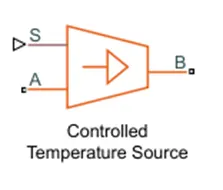
The Controlled Temperature Source block represents an ideal source of thermal energy that is powerful enough to maintain the specified temperature difference across the sources regardless of the heat flow consumed by the system.
3) Thermistor:
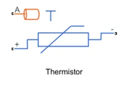
A Thermistor is a type of resistor whose resistance dependent on the temperature. The Thermistor block represent an NTC Thermistor using the B-parameter equation. The resistance at temperature T is R=R0eB(1/T−1/T0 .)
4) Resistance:
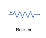
The voltage-current (V-I) relationship for a linear resistor is V=I*R, where R is the constant resistance in ohms.
5) Voltage Sensor:
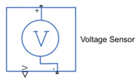
The block represents an ideal voltage sensor, that is, a device that converts voltage measured between any electrical connections into a physical signal proportional to the voltage.
6) Simulink PS Converter:
This block which help to connect between the Simulink to Simscape.
7) PS Simulink Converter:
This block which help to connect between the Simscape to Simulink.
8) Electrical Reference:
This block which is help given the electrical ground.
9) Battery:
This block help supply the electricity.
10) Solver Configuration:
The Solver Configuration block specifies the solver parameters that your model needs before you can begin simulation.
11) Display:
This block which display the Numerical value with respected to input.
12) Switch:
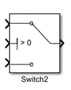
The Switch block passes through the first input or the third input signal based on the value of the second input. The first and third inputs are data input. The second input is a control input. Specify the condition under which the block passes the first input by using the Criteria for passing first input and Threshold parameters.
13) Thermal Reference:
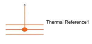
The Thermal Reference which helps to give the reference to thermal network where the temperature is absolute is zero.
14) Constant:
Output the constant specified by the 'Constant value' parameter.
Model Explanation:
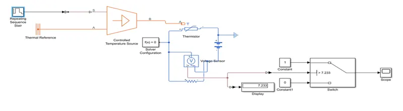
Step 1) The Repeating Sequence Stair is used for the give the input signal as per the required output.
Step 2) The Signal Builder is connected to the Simulink -PS Converter, where the Simulink- PS Converter which is used to converter input signal to physical signal.
Step 3) The Simulink- PS Converter is connected to the Controlled Temperature Source, this is connected to Thermistor and Thermal Reference where this block helps us to represents a reference point in a thermal network where the temperature is equal to absolute zero.
Step 4) For the Thermistor, electrical circuit are connected such as the Battery, Resistance, Voltage Sensor and Electrical Reference are connected to the Thermistor.
Step 5) The Solver Configurations used to solve the whole parameter before the beginning of the simulation.
Step 6) The voltage Sensor senses the temperature in the form of voltage and sends the data to its port
Step 7) Then Voltage Sensor is connected to the two PS-Simulink Converter, where it is useful for the converts the input Physical Signal to a Simulink output signal.
Step 8) The one PS-Simulink Converter which is connected to the Display.
Step 9) Another one which is connected to switch.
Step 10) The Switch is which is connected to the two constant block, if the constant block is indicated by the 1 means it is NO or if the constant block is indicated by 0 means it is off.
Step 11) The ON and OFF it is depended upon the threshold value, the threshold value is limited up to the 7.233.
Step 12) The Switch is connected to the Scope which is used to see output for given respected input.
Input:
Model of the Thermistor:
Input using the Repeating Sequence Stair:
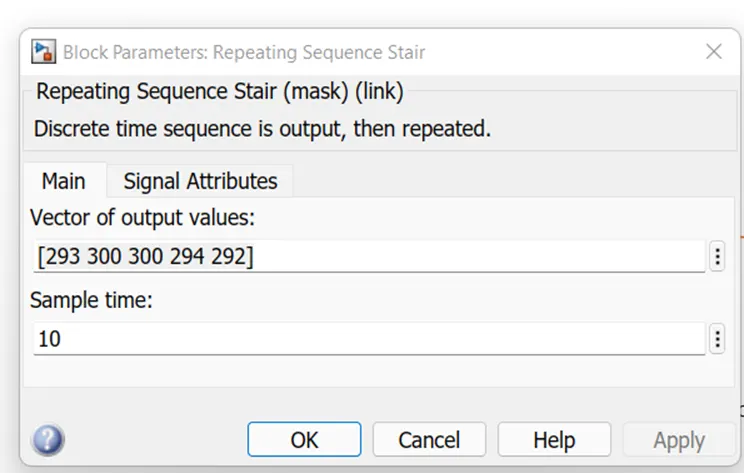
By using the Repeating Sequence Stair we can give the input to the thermistor block but where the sample time of 10.
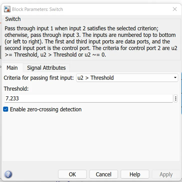
This is the threshold value for which the switch is going to operate.
Output:
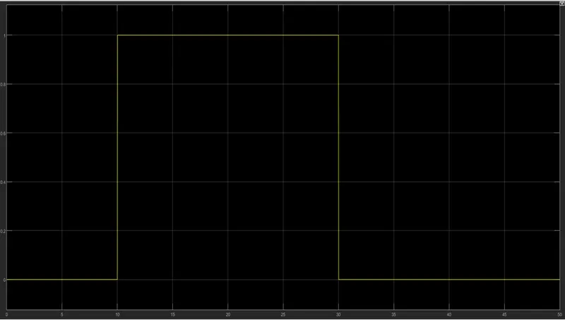
Now we seen that from 0-10 sec the fan is OFF because it is below the 25 C but between the 10-30 sec the fan is going to be NO. After the 30 sec the fan is going to OFF because the 23 C is the below the 25 C.
Conclusion:
We can conclude that by see above graph result that we complete simulation of the Thermistor with the respected condition.