Week -2
AIM:Make a Simulink model of Doorbell using solenoid block with the following details
In the above arrangement, when the switch is closed the electromagnet receives electrical power from the battery and pulls the metal arm to hit the bell producing sound.
Create a situation where the switch is closed for 2 seconds and then released. Observe the physical movement of the plunger.
Assume remaining parameters.
SOLUTION:
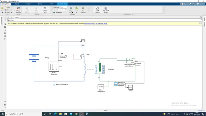
Explanation of the Block Digram of Door Bell:
- Simulink model of a Door Bell starts from Battery , its Cathode (postive) terminal is connected to switch and Anode (negative) terminal is connected to solenoid.
- In between Battery and switch a Pulse Generator is included to generate pulses it is also connected to switch through a medium Simulink to PS converter, Since the input Simulink signal has to be converted into a physical signal of the Pulse Generator.
- The Soenoid is also connected with Ideal Translational Sensor to sense the signal from solenoid.
- Finally to get the output of the block digarm Pulse Generator is conneted to scope and also Ideal Translational Sensor is connected to scope through a medium PS to Simulink converter to convert physical signal to output simulink signal.
- The block diagram 2 References Electrical & Mechanical Translational references
Batteries:
A Battery is a source of electric power consisting of one or more electrochemical cells with external connections for powering electrical devices.
Batteries convert chemical energy into electrical energy. Its positive terminal is the cathode and its negative terminal is the anode.
Pulse Generator:
A pulse generator is an electronic circuit or a piece of electronic test equipment used to generate rectangular pulses. Pulse generators are
used primarily for working with digital circuits, related function generators are used primarily for analog circuits.
Solenoid:
A solenoid is a device comprised of a coil of wire, the housing and a moveable plunger (armature). When an electrical current is introduced,
a magnetic field forms around the coil which draws the plunger in. More simply, a solenoid converts electrical energy into mechanical work.
Ideal Translational Sensor:
The Ideal Translational Sensor is a device that converts an across variable measured between two mechanical translational nodes into a control signal proportional to velocity or position. You can specify the initial position (offset) as a block parameter.
The sensor is ideal since it does not account for inertia, friction, delays, energy consumption, and so on.
Connections R and C are mechanical translational conserving ports that connect the block to the nodes whose motion is being monitored. Connections V and P are physical signal output ports for velocity and position, respectively.
The block positive direction is from port R to port C. This means that the velocity is measured as v = vR – vC, where vR, vC are the absolute velocities at ports R and C, respectively.
Switch:
A switch is controlled by an external physical signal. If the external physical signal PS is greater than the value specified in the Threshold parameter, then the switch is closed, otherwise the switch is open.
Electrical switches add discontinuities to your model, and therefore your choice of the solver can influence the model behavior. For detailed information about the solver settings, see Making Optimal Solver Choices for Physical Simulation.
Simulink-PS Converter:
The Simulink-PS Converter block converts the input Simulink signal into a physical signal. Use this block to connect Simulink sources or other Simulink blocks to the inputs of a Physical Network diagram.
To convey signal conversion while taking up minimal canvas space, the block icon changes dynamically based on whether it is connected to other blocks.
PS-Simulink Converter:
The PS-Simulink Converter block converts a physical signal into a Simulink output signal. Use this block to connect outputs of a Physical Network diagram to Simulink scopes or other Simulink blocks.
To convey signal conversion while taking up minimal canvas space, the block icon changes dynamically based on whether it is connected to other blocks.
Solver Configuration:
Each physical network represented by a connected Simscape block diagram requires solver settings information for simulation. The Solver Configuration block specifies the solver parameters that your model needs before you can begin simulation.
Each topologically distinct Simscape block diagram requires exactly one Solver Configuration block to be connected to it.
Scope:
Display signals generated during simulation.
2. Use a thermistor to sense the temperature of a heater & turn on or turn off the fan as per the below conditions
AIM:Make a simulink model for thermistor to sense the temperature of a heater & turn on or turn off the fan.
WHAT IS A THERMISTOR?
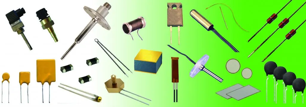
A thermistor is a resistance thermometer, or a semiconductor device whose resistance is dependent on temperature. The term is a combination of “thermal” and “resistor”. It is made of metallic oxides, pressed into a bead, disk, or cylindrical shape and then encapsulated with an impermeable material such as epoxy or glass.
There are two types of thermistors: Negative Temperature Coefficient (NTC) and Positive Temperature Coefficient (PTC). With an NTC thermistor, when the temperature increases, resistance decreases. Conversely, when temperature decreases, resistance increases. This type of thermistor is used the most.
A PTC thermistor works a little differently. When temperature increases, the resistance increases, and when temperature decreases, resistance decreases. This type of thermistor is generally used as a fuse.
Typically, a thermistor achieves high precision within a limited temperature range of about 50ºC around the target temperature. This range is dependent on the base resistance.
The thermistor symbols are:
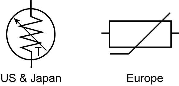
HOW DOES A THERMISTOR WORK IN A CONTROLLED SYSTEM?
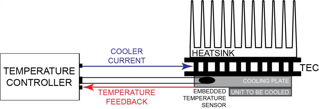
The main use of a thermistor is to measure the temperature of a device. In a temperature controlled system, the thermistor is a small but important piece of a larger system. A temperature controller monitors the temperature of the thermistor. It then tells a heater or cooler when to turn on or off to maintain the temperature of the sensor.
In the diagram below, illustrating an example system, there are three main components used to regulate the temperature of a device: the temperature sensor, the temperature controller, and the Peltier device (labeled here as a TEC, or thermoelectric cooler). The sensor head is attached to the cooling plate that needs to maintain a specific temperature to cool the device, and the wires are attached to the temperature controller. The temperature controller is also electronically connected to the Peltier device, which heats and cools the target device. The heatsink is attached to the Peltier device to help with heat dissipation.
Solution:
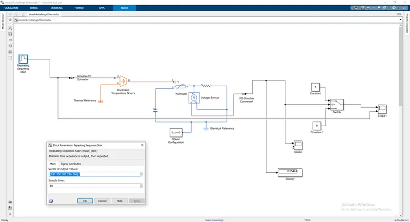
Thermistor with Repeating Sequence Stair(vector of output values & sample time):
Thermistor with stop time:
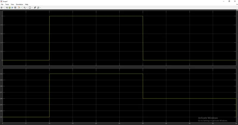
OUTPUT:
Explanation of the Block Digram of Thermistor:
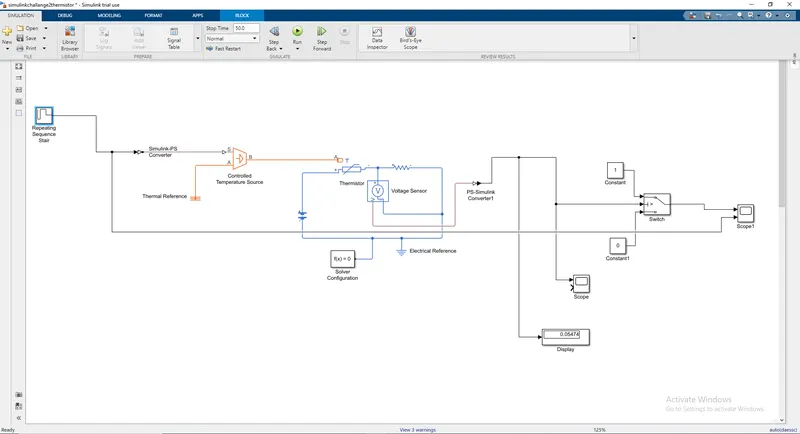
- Simulink model of a Thermistor starts from Repeating Sequence stair.
- Repeating Sequence stair is connected to Controlled Temperature Source through a medium Simulink-PS Convertor.
- Controlled Temperature Source has 3 terminals A,B, & S A is grounded to Thermal Reference, B is connected to Thermistor +ve terminal & S is connected to the medium Simulink-PS Convertor.
- Thermistor is connected with a Resistor & Battery in series and voltage sensor in parallel.
- An Electrical Reference is grounded to provide required solver configuration parameters.
- From voltage sensor one +ve terminal is connected with thermistor & -ve terminal with switch one terminal through a medium PS-Simulink Convertor.
- Other 2 terminals are connected with constant 0 & constant 1.
- Value should be enterered in Repeating sequence stair and the graph will be plotted.
- Finally switch is connected with scope where we will be getting Result as plotted above.
Repeating Sequence Stair:
The Repeating Sequence Stair block outputs and repeats a stair sequence that you specify with the Vector of output values parameter. For example, you can specify the vector as [3 1 2 4 1]' . A value in Vector of output values is output at each time interval, and then the sequence repeats.
Controlled Temperature Source:
The Controlled Temperature Source block represents an ideal source of thermal energy that is powerful enough to maintain specified temperature difference across the source regardless of the heat flow consumed by the system.
Thermal Reference:
The Thermal Reference represents a thermal reference point, that is, a point with an absolute zero temperature, with respect to which all the temperatures in the system are determined.
Thermistor:
A thermistor is a resistance thermometer, or a semiconductor device whose resistance is dependent on temperature. The term is a combination of “thermal” and “resistor”. It is made of metallic oxides, pressed into a bead, disk, or cylindrical shape and then encapsulated with an impermeable material such as epoxy or glass.
Simulink-PS Converter:
The Simulink-PS Converter block converts the input Simulink signal into a physical signal. Use this block to connect Simulink sources or other Simulink blocks to the inputs of a Physical Network diagram.
To convey signal conversion while taking up minimal canvas space, the block icon changes dynamically based on whether it is connected to other blocks.
Resistor:
A device that does not allow electric current to flow through it freely in a circuit.
Batteries:
A Battery is a source of electric power consisting of one or more electrochemical cells with external connections for powering electrical devices.
Batteries convert chemical energy into electrical energy. Its positive terminal is the cathode and its negative terminal is the anode.
Voltage sensor:
The Voltage Sensor represents an ideal voltage , that is, a device that converts voltage measured between two points of an electrical circuit into a physical signal proportional to the voltage.
Connections + and – are electrical conserving ports through which the sensor is connected to the circuit. Connection V is a physical signal port that outputs the measurement result.
PS-Simulink Converter:
The PS-Simulink Converter block converts a physical signal into a Simulink output signal. Use this block to connect outputs of a Physical Network diagram to Simulink scopes or other Simulink blocks.
To convey signal conversion while taking up minimal canvas space, the block icon changes dynamically based on whether it is connected to other blocks.
Electrical Reference:
The Electrical Reference represents an electrical ground. Electrical conserving ports of all the blocks that are directly connected to ground must be connected to an Electrical Reference block. A model with electrical elements must contain at least one Electrical Reference.
Switch:
The Switch passes through the first input or the third input signal based on the value of the second input. The first and third inputs are data input. The second input is a control input. Specify the condition under which the block passes the first input by using the Criteria for passing first input and Threshold parameters.
Scope:
Display signals generated during simulation.