Week -2
1.
Aim: To make a simulink model of door bell using solenoid and observe its physical movement of plunger.
Procedure: A door bell is a device that uses electrical energy and converts it to mechanical energy and produce sound. the door bell consist of a solenoid which has a plunger that that moves in accordance with fleming's left hand rule when current flows through the conductor across it and produce a magnetic field. the movement of plunger then produces sound when it hit a metal.
Explanation:
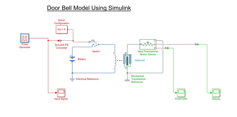
To observe the physical motion of plunger in simulink we use the following components.
a. Switch: A device that connects and disconnects a circuit based on an input signal.
b. Inputs
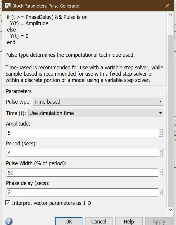
b1. Pulse generator: The pulse generator produces a square wave of 2 second interval to close the switch and open it after 2 seconds. Here the pulse generator produces and pulse of pulse width 50% of total time period of 4 second with amplitude 5. A phase delay of 2 seconds is produced so that in 1st 2 seconds output is zero and for next 2 seconds produce an output of amplitude 5.
b2. Battery: A battery is an device that gives required power to drive the solenoid. A battery of 24V is used.
c. Solenoid: A solenoid is a device with electrical connections and produce and mechanical linear motion. A solenoid with default parameters are used except the change of motion direction set to move away from port c to get a +ve value. 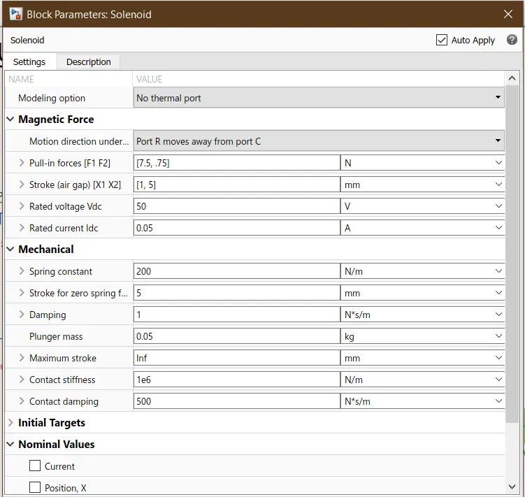
d. converters : a simulink to ps converter is used for converting a simulink signal to physical signal. A ps to simulink converter is used to convert a physical signal to simulink signal and obtain output.
e. References: An ideal electrical reference is connected to electrical side and an ideal mechanical translational reference is used in the layout. a solver configuration is also used in the input side.
f. Outputs
f1. Ideal mechanical translational reference: This block works as a motion sensor and senses the motion of plunger in solenoid.
f2. Scope: there are 3 scopes used in the circuit. It generats output signals of position and velocity.
a scope is also connected to input signal to verify the input.
Simulink Model for Door bell
Results
The simulation is made to run for 10 seconds and results from scope are as follows.
1. Input Signal
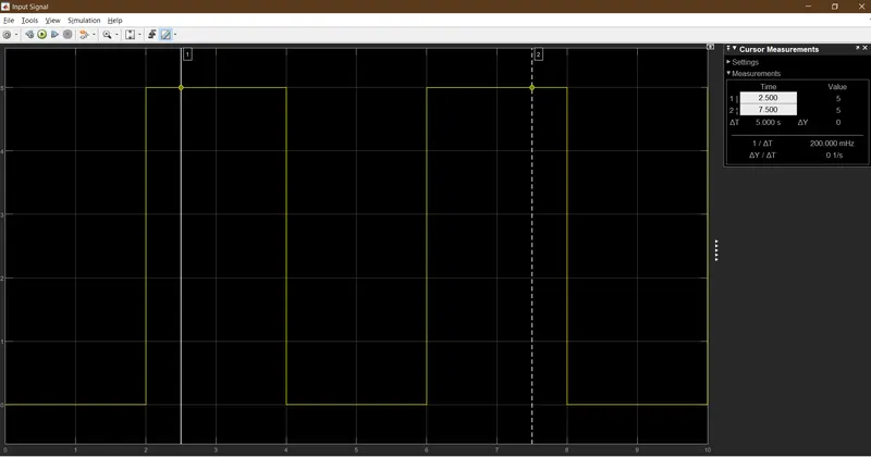
An input pulse of 2 second delay of amplitude 5 is applied for 2 seconds and then turned off for another 2 seconds.
2. Outputs
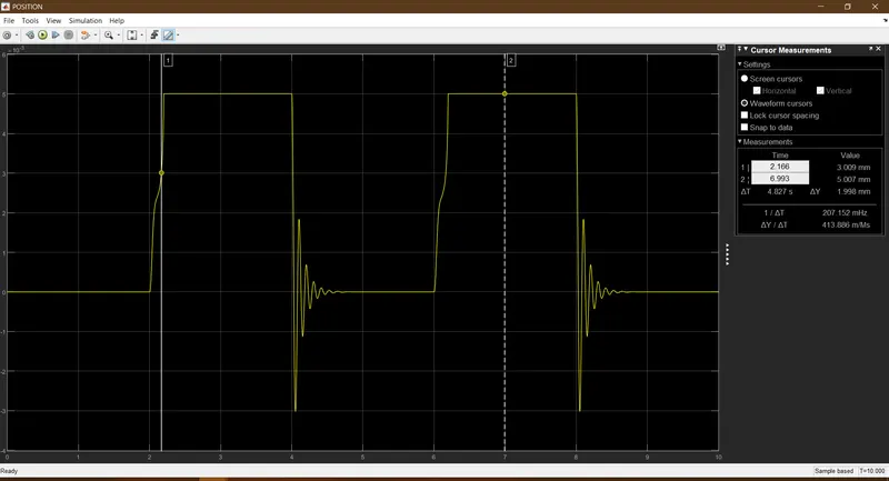
The ouput shows the movement of plunger in the solenoid block when switch turns on.
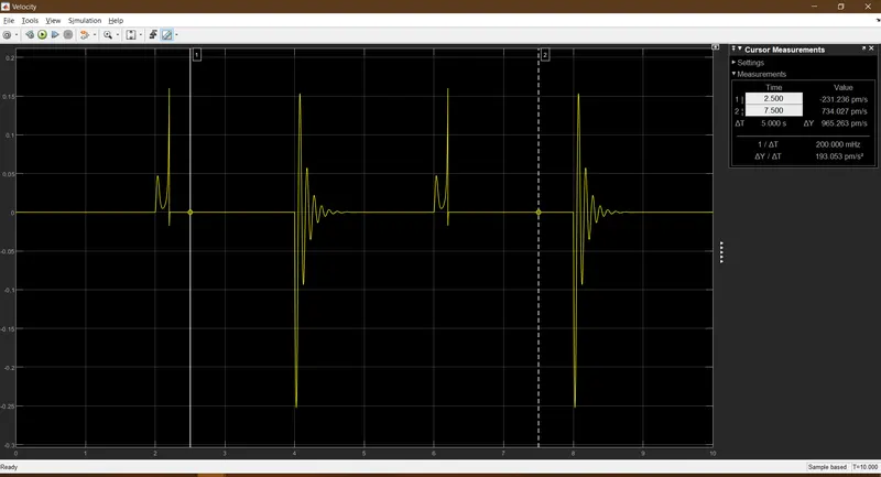
The ouptut shows the velocity vs time graph for movement of plunger.
Result
From the above grpahs its can be observed that the plunger of solenoid starts to move with a delay of 2 seconds and then stays for another 2 seconds hiting the bell and returns backs to its original position.
2.
Aim: To use a thermistor to sense the temperature of a heater and turn on the fan when temperature exceeds 25°C and turn off otherwise
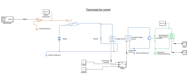
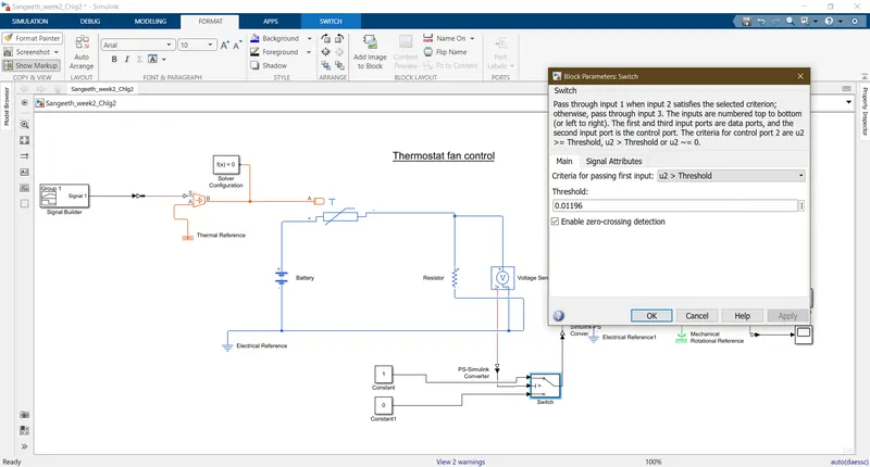
Procedures: A thermistor is a type of resistor which changes its resistor according to temperature. The simulink diagram consist of 3 parts, thermal circuits, electrical circuit and mechanical part. The specified temperature is provided to a thermistor and voltage across resistance is calculated to operate and switch and runs the fan.
Explanation
Input Signal:
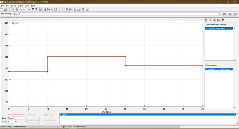
The input signals are given by signal builder in the input. the input signals are given in kelvin (20°C,27°C,23°C) and is connected to Simulink PS convertor. It is then connected to controlled temperature source block and then into thermistor.
The Electrical input power for the circuit is given by a battery and a resistor is connected in series with thermistor. The voltage across resistor is measured to determine the temperature of heater.
A solver configuration and an electrical reference to the circuit is also provided.
Switch
The voltage for the voltmeter is connected to the switch to check and satisfy the condition. The voltage threshold for 25°C, is found before to input as switch condition. if the temperature exceeds the threshold, gives out zero, if it is below the threshold, it gives the output value signal.
Output
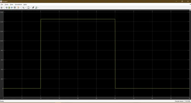
The pulse generated from switch is given as input to DC motor through a controlled voltage source towards armature of motor which runs the fan. the angular motion of motor is measured using scope. Rotational reference and solver configuration is provided to circuit
Conclusion
It can be inferred that the fan shows displacement when temperature exceeds 25 °C and hence conditions are satisfied.