Week -2
- Make a Simulink model of Doorbell using solenoidblock with the following details:
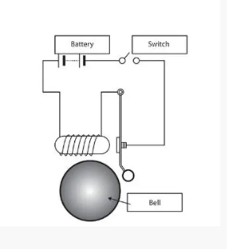
in the above arrangement, when the switch is closed the electromagnet receives electrical power from the battery and pulls the metal arm to hit the bell producing sound.
Create a situation where the switch is closed for 2 seconds and then released. Observe the physical movement of the plunger.
- Solution: -
See the above fig. doorbell this work on the principal of Faraday’s low of electromagnetic induction. If the battery supply on then closes the switch and current will be flow through the circuit, the magnetic flux is produced inside the coil and plunger are operate and metal arm use to hit the ball & produce sound.
Also, see the construction diagram of the doorbell. Basically, doorbell is electromagnetic device because these devices convert electrical energy into mechanical energy (soft iron strip & hammer hit the bell and create sound).
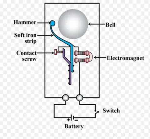
Fig(a): Construction of Doorbell
- Simulink model of Doorbell useful solenoid block
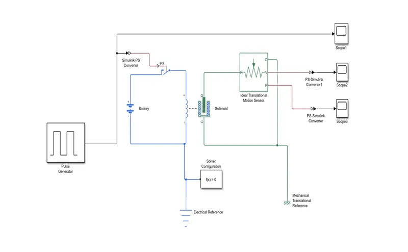
- SIMULINK MODEL EXPLANATION: -
- Pulse Generator: - The Pulse Generator block generates square wave pulses at regular intervals. The block waveform parameters, Amplitude, Pulse Width, Period, and Phase delay, determine the shape of the output waveform.
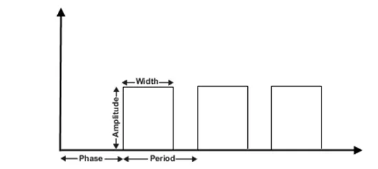
Fig(b): Pulse Generator
- Battery: It gives the power to the close loop.
- PS-Simulink Converter: It Converts physical signal into Simulink output signal.
- Electrical reference: It shows a Connection to electrical ground.
- Mechanical Translational References: Reference connection for mechanical translational ports
- Solenoid: Electrical characteristics and generated force of solenoid.
- Switch: Switch controlled by an external physical signal.
- Simulink-PS Converter: It Converts the Simulink input signal into a physical signal.
- Ideal translational Motion Sensor: It is a motion sensor in mechanical translational systems.
- Scope: it displays signals generated during simulation.
- Input Waveform: -
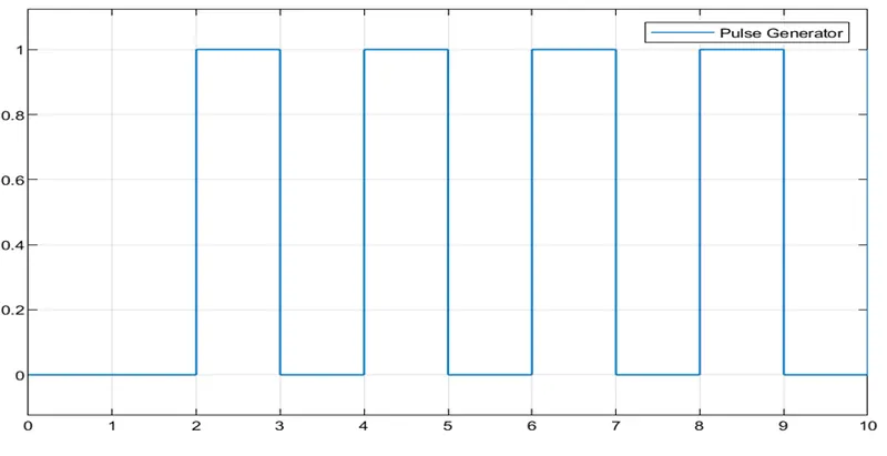
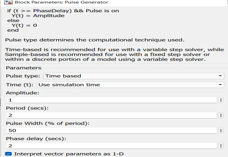
Fig(c) Input Waveform
We can see fig (c) the input waveform if the amplitude is 1, time period is 2 sec, pulse width 50% of period & phase delay 2 sec.
- Output Waveform: -
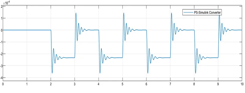
- Result: -
We can see all the result; the switch is closed solenoid are active & metal arm are operated and to hit the bell producing sound.
The motion of the plunger was simulated recorded & plotted by using any ideal motion sensor and scope.
- Use a thermistor to sense the temperature of a heater & turn on or turn off the fan as per the below conditions:
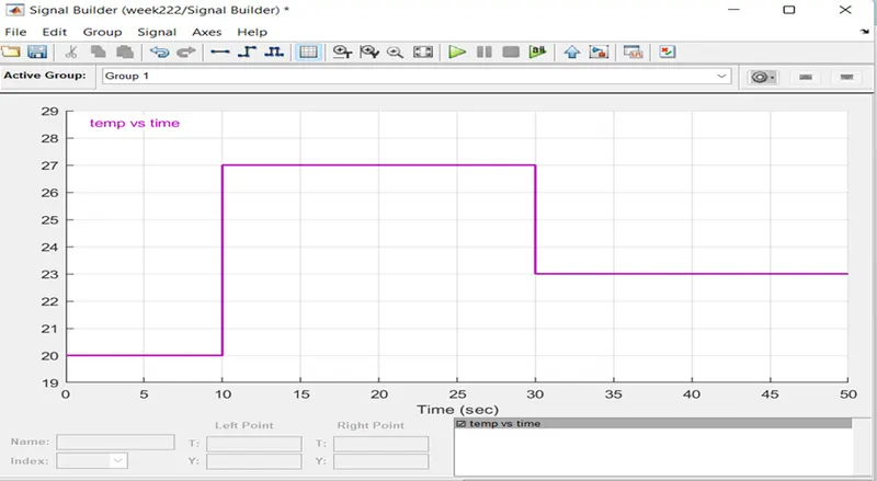
Temperature source: 20 °C from 0 to 10 seconds, 27 °C from 10 to 30 seconds, 23 °C from 30 to 50 seconds
Fan conditions: ON if the temperature above 25 °C, OFF otherwise.
- Solution: -
Thermistor: -
A thermistor is a type of resistance is strongly dependent on temperature, more so than in standard resistors. The world is a combination of thermal & resister.
Thermistor are two type Negative temperature coefficient thermistor (NTC). & Positive temperature coefficient thermistor (PTC).
NTC: Negative temperature coefficient thermistor resistance decreases as the temperature increases.
PTC: Positive temperature coefficient thermistor resistance increases as the temperature increases.
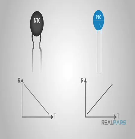
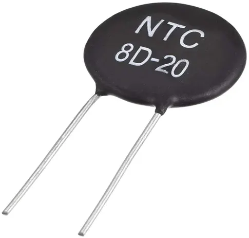
Thermistor
- Simulink model for Fan controlled by a thermistor
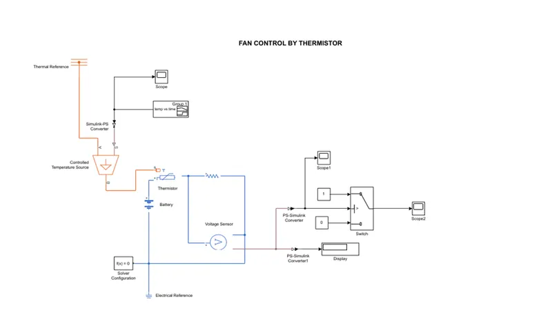
SIMULINK MODEL EXPLANATION: -
Signal builder: -
In this signal builder 0 to 10 sec Temperature are 20°C, 10 to 30 sec temperature are 27°C & 30 to 50 sec temperature 23°C.
Controlled Temperature Source: -
The Controlled Temperature Source block represents an ideal source of thermal energy that is powerful enough to maintain specified temperature difference across the source regardless of the heat flow consumed by the system. Connections A and B are thermal conserving ports corresponding to the source inlet and outlet, respectively. Port S is a physical signal port, through which the control signal that drives the source is applied
Thermistor: -
A thermistor is a type of resistor whose resistance is dependent on temperature. more so than in standard resistors the word is a combination of thermal and resistor The Thermistor block represents an NTC thermistor using the B-parameter equation
NTC-Negative Temperature Co-efficient
Resistor: -
The Resistor block models a linear resistor described with the following equation:
V=I-R
Were,
V-Voltage.
I-Current.
R-Resistance
Voltage Sensor: -
The Voltage Sensor block represents an ideal voltage sensor, a device that converts voltage measured between two points of an electrical circuit into a physical signal proportional to the voltage.
Voltage Source: -
The Voltage Source block implements a voltage source with DC, AC, and noise components.
Electrical Reference: -
The Electrical Reference block represents an electrical ground. Electrical conserving ports of all the directly connected blocks to the ground must be connected to an Electrical Reference block. A model with electrical elements must contain at least one Electrical Reference block.
Input Waveform: -
Output Waveform: -
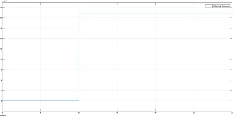
- Result: -
Create Simulink model used Thermistor to sense temperature & turn on and off fan as per above condition.