Week -2
SECTION A
1 Objective:-
- Make a Simulink model of Doorbell using a solenoid block with the following details:
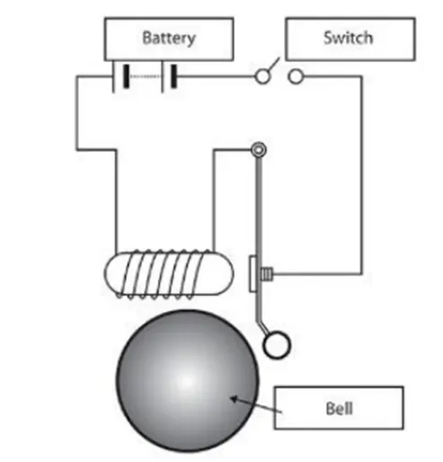
In the above arrangement, when the switch is closed the electromagnet receives electrical power from the battery and pulls the metal arm to hit the bell producing sound.
Create a situation where the switch is closed for 2 seconds and then released. Observe the physical movement of the plunger.
Solution:-
THEORY:-
#Solenoid:-
- A solenoid is a three-dimensional structure of wire.
- When this wire is wrapped around a metallic block in a coil and current passed through it it has some special magnetic properties Electromagnetic induction makes it an electromagnet that can be switched on or off.
- The side in which the current appears to be passing clockwise is the South Pole and the side in which the current seems to be passing anticlockwise the Northern Pole.
- The solenoid works just like a bar magnet and therefore has many uses.
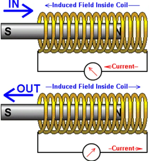
Figure 1.1 Construction of Solenoid
#Doorbell:-
- The doorbell is a device having mechanical and electrical component produce sound by pressing the switch.
- When the switch is pressed, the circuit loop is complete which causes the current to flow through the circuit, while passing the Solenoid it generates the electromagnet at desired space, which allows the plunger to move, due to which it hots the bell and produce sound.
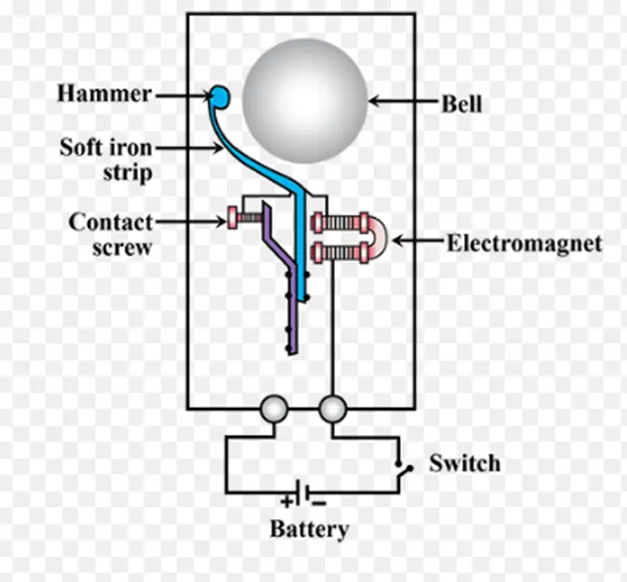
Figure 1.2 Construction of Doorbell
INPUT:-
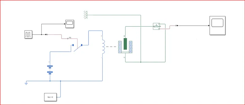
Figure 1.3 Simulink model of Doorbell useful solenoid block
SIMULINK MODEL EXPLANATION:-
- Pulse generator: The Pulse Generator block generates square wave pulses at regular intervals. The block waveform parameters, Amplitude, Pulse Width, Period, and Phase delay, determine the shape of the output waveform.
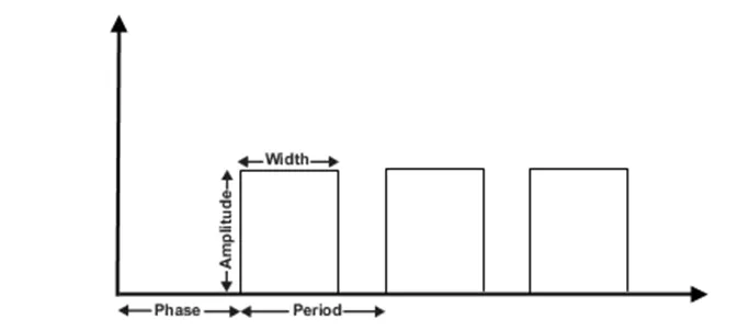
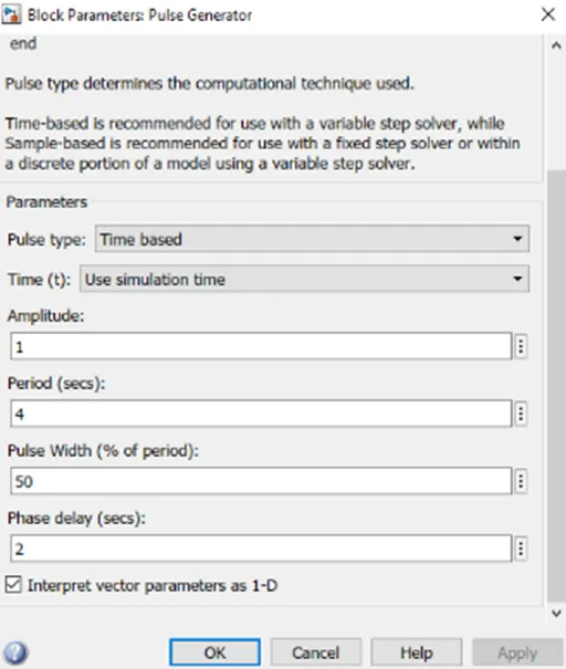
Figuer 1.4 Pulse generator
- Battery: It gives the power to the close loop.
- PS-Simulinik Converter: It Converts physical signal into Simulink output signal.
- Electrical reference: It shows a Connection to electrical ground.
- Mechanical Translational References: Reference connection for mechanical translational ports
- Solenoid: Electrical characteristics and generated force of solenoid.
- Switch: Switch controlled by an external physical signal.
- Simulink-PS Converter: It Converts the Simulink input signal into a physical signal.
- Ideal translational Motion Sensor: It is a motion sensor in mechanical translational systems.
Input Waveform:-
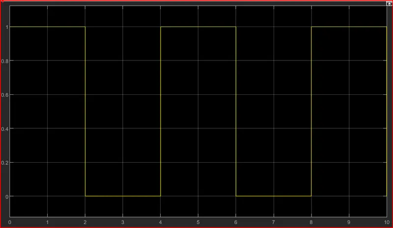
Figure 1.5 Input Waveform
Output Waveform:-
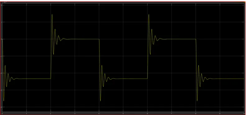
Figure 1.6 Output Waveform
RESULT:-
In the above results, the switch is closed the electromagnet receives electrical power from the battery and pulls the metal arm to hit the bell producing sound.
The motion of the plunger was simulated and recorded and plotted by using an ideal motion sensor and scope.
SECTION B
2 Objective:-
- Use a thermistor to sense the temperature of a heater & turn on or turn off the fan as per the below conditions:
Temperature source: 20 °C from 0 to 10 seconds, 27 °C from 10 to 30 seconds, 23 °C from 30 to 50 seconds
Fan conditions: ON if the temperature above 25 °C, OFF otherwise
Solution:-
THEORY:-
THERMISTOR:-
A thermistor is a resistance thermometer or a resistor whose resistance is dependent on temperature. The term is a combination of "thermal" and "resistor. It is made of metallic oxides, pressed into a bead, disk, or cylindrical shape and then encapsulated with an impermeable material such as epoxy or glass.
Thermistors are easy to use, inexpensive, sturdy, and respond predictably to changes in temperature. While they do not work well with excessively hot or cold temperatures, they are the sensor of choice for applications that measure temperature at the desired base point. They are ideal when very precise temperatures are required.
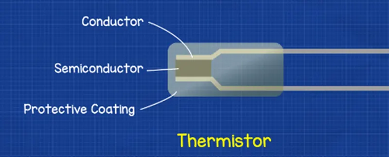
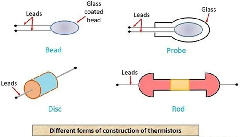
Figure 2.1 Different forms of construction
of thermistors
Temperature Range:
The approximate overall range of temperatures in which a sensor type can be used. Within a given temperature range, some sensors work better than others.
INPUT:-
Simulink model for Fan controlled by a thermistor
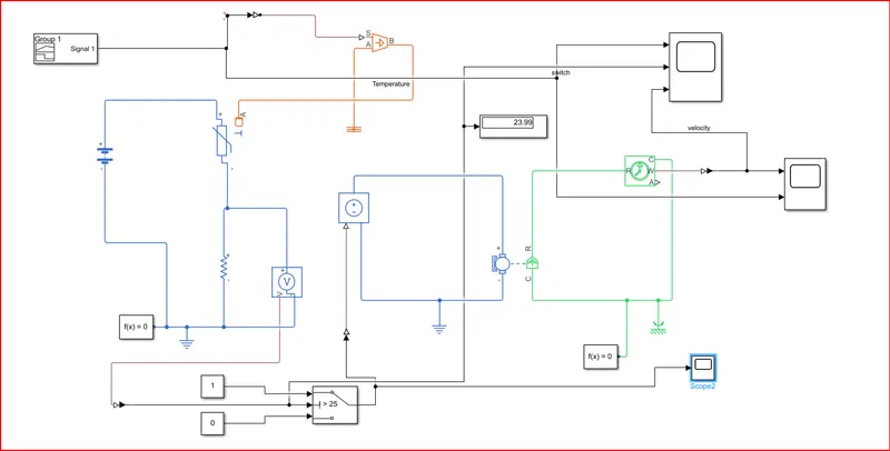
controlled by a thermistor
SIMULINK MODEL EXPLANATION:-
Firstly we have to convert the temperature degree Celcius ( °C ) into kelvin (K)
|
Sr. No. |
At position |
Time (second) |
Temperature (Kelvin) |
|
1 |
At point 1 |
0 second |
293 K |
|
2 |
At point 2 |
10 second |
293 K |
|
3 |
At point 3 |
10 second |
300 K |
|
4 |
At point 4 |
30 second |
300 K |
|
5 |
At point 5 |
30 second |
296K |
|
6 |
At point 6 |
50 second |
296 K |
Signal Builder block is used to input the values as per given conditions
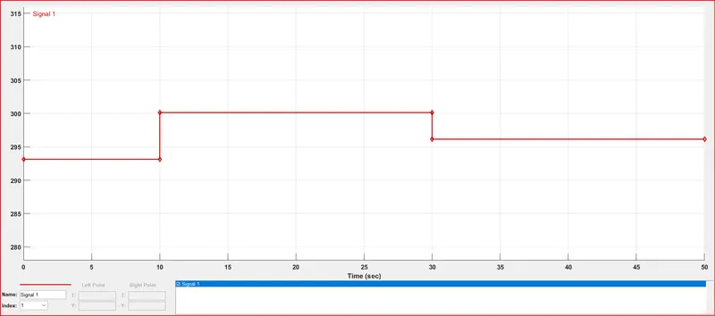
Figure 2.3 Signal Builder Block
Controlled Temperature Source:-
The Controlled Temperature Source block represents an ideal source of thermal energy that is powerful enough to maintain specified temperature difference across the source regardless of the heat flow consumed by the system. Connections A and B are thermal conserving ports corresponding to the source inlet and outlet, respectively. Port S is a physical signal port, through which the control signal that drives the source is applied
Thermistor:-
A thermistor is a type of resistor whose resistance is dependent on temperature. more so than in standard resistors The word is a combination of thermal and resistor The Thermistor block represents an NTC thermistor using the B-parameter equation
NTC-Negative Temperature Co-efficient
Resistor:-
The Resistor block models a linear resistor described with the following equation:
V=I-R
Where,
V-Voltage.
I-Current.
R-Resistance
Voltage Sensor:-
The Voltage Sensor block represents an ideal voltage sensor, a device that converts voltage measured between two points of an electrical circuit into a physical signal proportional to the voltage.
Voltage Source:-
The Voltage Source block implements a voltage source with DC, AC, and noise components.
Electrical Reference:-
The Electrical Reference block represents an electrical ground. Electrical conserving ports of all the directly connected blocks to the ground must be connected to an ElectricalReference block. A model with electrical elements must contain at least one Electrical Reference block.
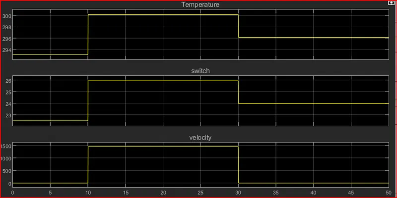
fig no. temprature,voltage, fan
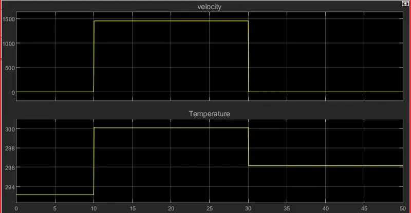
Figure 2.4 Input waveform
RESULT:-
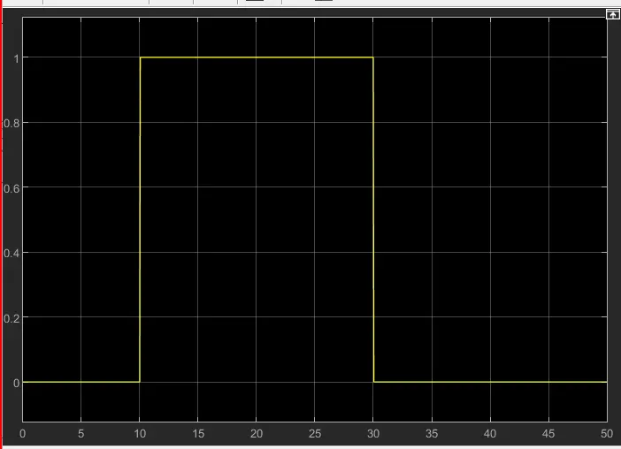
(Fan conditions: ON if the temperature above 25 "C. OFF otherwise)
- A thermistor is used to sense the temperature of a heater & turn on or turn off the fan as per the above conditions
- Therefore the fan conditions are executed by SWITCH block and plotted in scope block.