Week 2- 2R Robotic Arm Challenge
Aim-:
Write a program in Matlab to simulate the forward kinematics of a 2R Robotic Arm.
Introduction -:
Kinematics is the relationships between the positions,velocities and accelerations of the links of a manipulator
Forward kinematics refers to process of obtaining position and velocity of end effector, given the known joint angles and angular velocities. For example, if shoulder and elbow joint angles are given for arm in sagittal plane, the goal is to find Cartesian coordinates of wrist/fist.
The links are the rigid members connecting the joints. The joints (also called axes) are the movable components of the robot that cause relative motion between adjacent links.
Each joint or axis provides a certain degree of freedom of motion.
The complexity of any robotic arm can be determined by the total number of degrees of freedom associated with each link.
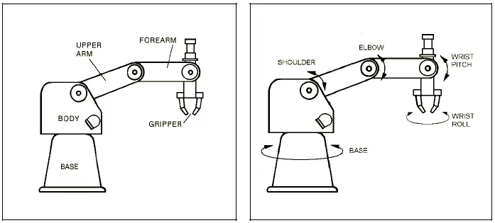
Figure 1 shows the represenstation and placements of frames/links and joints.
Formula for calculating the link arm-:
Compute the position and orientation of an end-effector in terms of the joint angles.

CODE-:
clear all
close all
clc

% Inputs
l1 = 1
l2 = 0.4

theta1 = linspace(0,90,40)
theta2 = linspace(0,90,40)

ct=1

for i = 1:length(theta1)
    THETA1 = theta1(i)

for j = 1:length(theta2)
    THETA2 = theta2(j)

 % Cordinates

 x0 = 0
 y0 = 0

 x1 = l1*cosd(THETA1)
 y1 = l1*sind(THETA1)

 x2 = x1 + l2*cosd(THETA2)
 y2 = x2 + l2*sind(THETA2)

 % Plotting

 plot([x0 x1],[y0 y1],[x1 x2],[y1 y2],'linewidth',3)
 axis([-0.1 1.5 0 1.5])
 pause(0.03)
 M(ct) = getframe(gcf)
 ct=ct+1

end
end

movie(M)
videofile=VideoWriter('forward kinematics.avi', 'uncompressed avi');
open(videofile)
writeVideo(videofile,M)
close(videofile)
EXPLANATION OF THE CODE-
Starting the code with clear all,close all and clc commands since
Clear all-This clears your workspace, closes all figures, and clears command window.
Close all-close all closes all figures whose handles are visible.
clc - clears all inputs and outputs from the command window.
Step 1 -: Define the inputs
First we start with defining the inputs of the pre requisite parameters (which are the lenghts of arm 1 and arm 2)
The value of both theta 1 and theta 2 are defined by using the linspace command to enable the code to simulate the positiions of arms at diffrent angles at diffrent point of time
the value given is linspace(0,90,40),this will give the 40 values of theta 1 and theta 2 between the range of 0-90 degrees
Step 2-: Setting up the counter
A counter is a variable that counts an event in a loop. A 'for' loop was used which is the repetetion control structure that allows you to efficiently write a loop that needs to execute a specific number of times.
For theta 1 'i' variable was assigned
For theta 2 'j' variable was assigned
A seperate variable 'j' was assigned for theta 2 to give theta 2 its own respective angle.
Step 3-: Plotting
Next step is to plot the graph for all the x and y cordinates with axis shown in figure
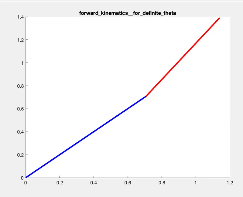
A pause command was used for pausing the command for certain seconds (0.03sec).
The M command was used to capture the current frame everytime the for loop runs. The final step is to add the +1 to the counter (ct) variable to increase the frame by 1 everytime the loop runs
Step 4-: the final step is to create the movie of the robotic arm so the 'movie' command was was used.
The VideoWriter command was used to assign the video format,for this project the .avi format was used .
open command was used to open the video.
writeVideo command was used to open the video with plot frames.
The close command was used to close the video file.
Error faced- Despite of writing the correct program and succesfully compiling it with the animation,the video file is not showing in the laptop,therefore a recorded video of my animation is attatched with the google drive. https://drive.google.com/file/d/1JDA_gf8g-k6lCXtfch1dxzLAbcGXEkt-/view?usp=drivesdk