Week 2- 2R Robotic Arm Challenge
AIM-
*MATLAB program for simulated the forward kinematics of a 2R robotic arm
INTRODUCTION-
*Forward kinematics refers to the use of the kinematic equations of a robot to compute the position of the end-effector from specified values for the joint parameters
*In industries like automobile industries and aviation all the processes are now days automatically done by robot. So, at the design stage of robot designer need to know the workspace of the robot for particular operation, so by software like MATLAB designer can easily know range of robot by inserting different size of robotic arm and different angles of robotics arm with reference surface
GOVERNING EQUATION-
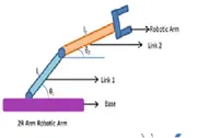
As per the image mention above L1(1m) & L2(0.5m) are two links of the arm which makes θ1& θ2 angle with horizontal axis respectively
*Co-ordinates of link1
Starting point = [X0 ,Y0]=[0,0]
Ending point =[X1 , Y1] = [L1Cosdθ1,L1Sind θ2]
*Co-ordinates of Link2
Starting point=[X1,Y1] = [L1Cosd θ1,L1Sind θ1]
Ending point= [X2,Y2] = [X1+L2Cosd θ2, Y1+L2 θ2]
OBJECTIVE
We will take multiple values of θ1 & θ2 range from 0 to 90 and by all different combination of those values and plots will be created and at the end of stitching all the plots together to make a animation
Program
clear all
close all
clc

%inputs
l1=1;
l2=0.5;

%angle of both links with horizontal axis
theta1=linspace(0,90,10);
theta2=linspace(0,90,10);

ct=1;
for i=1:length(theta1)
    THETA1=theta1(i);
   for  j=1:length(theta2)
    THETA2=theta2(j);
    x0=0;
    y0=0;
    x1=l1*cosd(THETA1);
    y1=l1*sind(THETA1);
    x2=x1+l2*cosd(THETA2);
    y2=y1+l2*sind(THETA2);

    plot([x0 x1],[y0 y1],[x1 x2],[y1 y2],'linewidth',3,'color','g');
    axis([-0.1 1.5 0 1.5])
    title('kinematic of 2R robotics arm')
    xlabel('arm movement in xaxis');
    ylabel('arm movement in yaxis');
    grid on
    pause(0.1)
    file_text=sprintf('robotics_animation%d.png',ct);
    saveas(gca,file_text);
    M(ct)=getframe(gcf);
    ct=ct+1;
   end
end
movie(M)
videofile = videoWriter('forward_kinematics.avi','uncompressed AVI');
open(videofile)
writevideo(videofile,M)
close(videofile)
First of all the inputs should be provided
% Length of link
l1=1
l2=0.5
% Angle of both links with horizontal axis
Theta1=linspace(0,90,10)
Theta2=linspace(0,90,10)
By using the command 10 values for theta will be calculated which is starting from 0 up to 90 degree
For i = length (theta1);
Values of i will change from 1 to the lenth (theta10 , length(theta1) is nothing but all the 10theta values between 0to 90 , which is generated by linspace command
THETA1=theta1(i);
THETA1 is a variable where theta1 is a array, i is loop counter which determine how many times forloop get executed
For each value of theta1 theta 2 has to change 10 values
For j = 1: length (theta2)
THETA2=theta2(j)
X0=0;
Y0=0;
X1=l1*cosd(THETA1)
Y1=l1*sind(THETA1)
X2=x1+l2*cosd(THETA2)
Y2=y1+l2*sind(THETA2)
plot ([x0 x1],[y0 y1],[x1 x2],[y1 y2],’linewidth’,3,'color','g');
By this command plot will be generated, in which linewidth and color is specified
Axis ([-1.5 1.5 0 1.5])
Pause(0.3)
Grid on
File_text=sprint(‘robotics_animation%d.png’,ct)
Saveas(gca,file_text);
Print f command to change the file name
Tis will result in saving the entire output file in the present
Ct=ct+1
Increment forloop execution
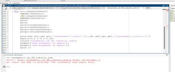
Error
1st Error—we had to write clear all starting with small c and not with capital C
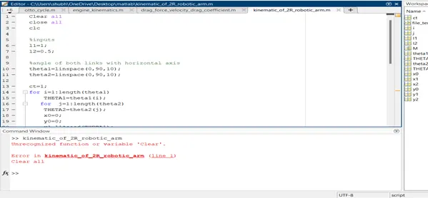
2nd Error—missing the theta 1 in the i loop,due to which plots wew generated for final position.
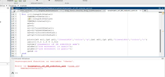
3rd Error—missing to add for loop for the j loop due to which robotics arm made in multiple form in the plot
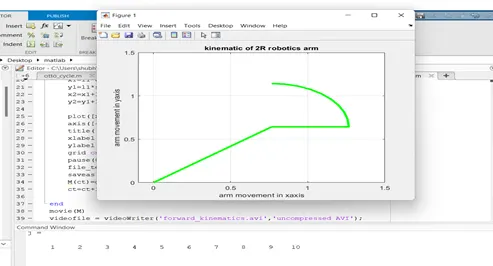
4th Error—Adding 2 end command in the program for the i and j loop for closing both the loop
The video file has been uploaded to YouTube link is given below
https://youtu.be/ftVJ8Vevw7U
Conclusion—
*After generating animation by examine closely we can understand the workspace of the robotics arm which is our main purpose.
*By changing length & angle of the links different combination are possible , plotting graphs for all those different combination robot design can be done