Week -2
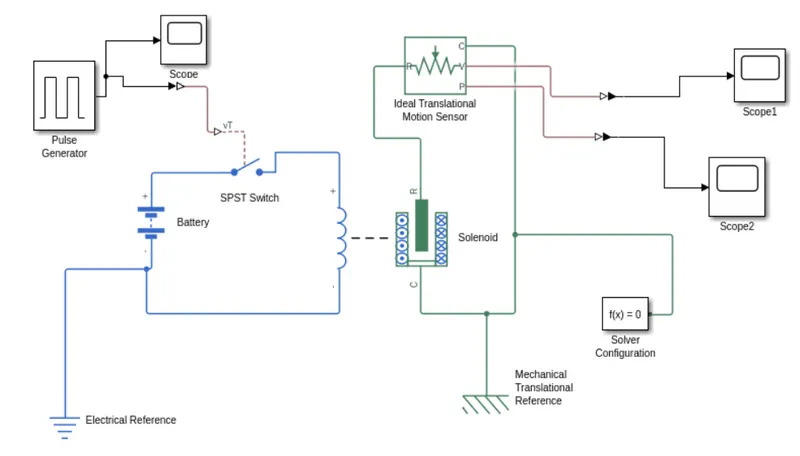
1) To make a Simulink model of Doorbell using Slenoid block.
* Simulink model block diagram:
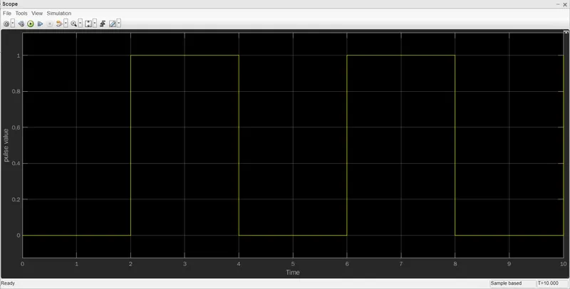
* Result_1:
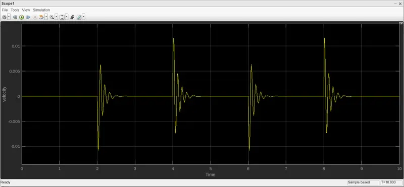
* Result_2:
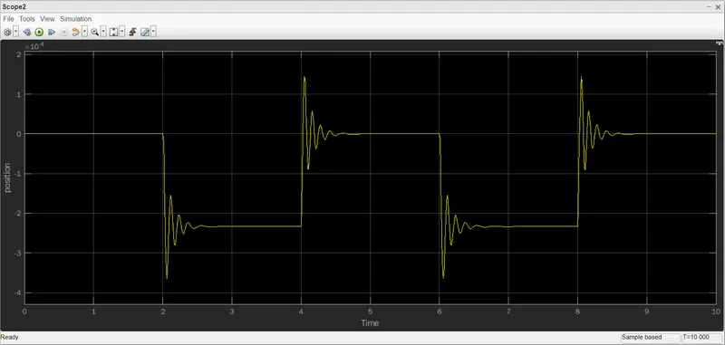
* Result_3:
* Blocks Used:
*) Pulse Generator: The Pulse Generator block generates sqaure wave pulses at regular intervals. The block waveform parameters, amplitude, pulse width, period and phase delay determine teh shape of the output waveform.
*) Scope: Display signals generated during simulation.
*) Simulink PS Converter: Converts the Simulink input signal to a Physical Signal.
*) SPST Switch: Single-Pole-Single-Throw-Switch,the block is controlled by an external control signal vT. If vT is greater than the threshold, then the switch is closed, otherwise, the switch is open.
*) Battery: It is a stored electrical source for the electrical unit.
*) Electrical Reference: The block represents an electrical ground.
*) Solenoid: The Solenoid block represents the electrical characteristics and generated force for the solenoid. The solenoid block represents port R moves towards port C.
*) Mechanical Translational Reference: The Mechanical Translational Reference block represents a reference point, for all mechanical translational ports.
*) Solver Configuration: The Solver Configuration block specifies the solver parameters that your model needs before you can begin the simulation.
*) Ideal Translational Motion Sensor: It acts as a Motion sensor in mechanical translational systems.
*) PS Simulink Converter: Converts the input Physical Signal to a Simulink output signal.
* Working:
*) Pulse Generator creates an input signal of pulse with 1 unit amplitude, 4 sec period, having 50% pulse width with 2 sec delay for the model.
*) Then we add scope to it so that we can compare the inputs adn the outputs of the model.
*) Then the input signal is connected to the Simulink PS Converter which converts the simulink signal to a physical signal which is then sent towards the SPST Switch.
*) After recieving the physical signal, the SPST Switch compares it with its threshold value if it is greater than it, then it closes the electric circuit, or else it is open.
*) After the electric circuit is closed the current is flown frm the circuit and then it energies the solenoid connected to teh battery.
*) As the solenoid is changed it pulls the port R towards the port C.
*) A Mechanical Translational Reference is attached to the port R of the Solenoid to understand teh position and velocity of the plunger of the solenoid.
*) To record its position and velocity PS Converter converts the physical signal to a Simulink signal and then scope block we record it for the simulation duration.
2) To use a thermistor to sense the temperature of a heater and turn on or turn off the fan as per the given conditions.
* Simulink Model Block Diagram:
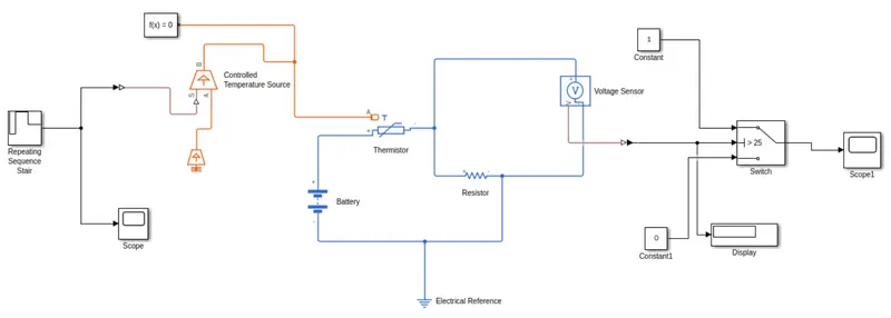
* Blocks Used:
*) Repeating Sequence Stair: In this block the discrete time sequence is output, then repeated.
*) Scope: Display signals generated during simulation.
*) Solver Configuration: The Solver Configuration block specifies the solver parameters that your model needs before you can begin the simulation.
*) Controlled Temperature Source: This block represents an ideal energy source in a thermal netwrok that can maintain a controlled temperature deifference regardless of the heat flow rate.
*) Thermistor:This block represents an NTC thermistor using the B-parameter equation.
*) Battery: It is a stored ekectrical source for the electrical circuit.
*) Electrical Reference: The Electrical Reference block represents an electrical ground.
*) Resistor: In this block the positive and negative terminals of the resistor are denoted by the + and - signs respectively. By convention the voltage across the resistor are denoted is given by V(+)-V(-), and the sign of the current is positive to the negative terminal.
*) Voltage Sensor: This block represents an ideal vlotage sensor, that is, a device that converts voltage measured between any electrical connections into a physical signal proportional to the voltage.
*) Constant: This block specifies the 'Constant Value' parameter.
*) Display: This block displays the output of the simulation.
*) Switch: This block acts as a typical switch. The first and the third inputs are data ports and the second port is the control port.
* Working:
*) We give the temperature inputs at every 10 seconds, that is for 50 seconds, we give temperatures at Kelvin. Temperature are 293, 300, 300, 296, 296 for every 10 seconds.
*) Add signal repeating stair block for input temperatures. Give temperatures as above and sample time as 10 seconds. Here sample time means, each value temperature at a certain time period.
*) Give scope for knowing the input plot of it.
*) Add cintrolled temperature source block for maintaining temperature. Join the satir block to controlled temperature source with the help of Simulink PS Converter.
*) Add temperature reference block and join with the point A.
*) Add thermistor block and join the point A with point B of the source block.
*) Add battery block for source to pass the current in the circuit.
*) Add vlotage sensor block and ressitor block andjoin the thermistor. Add an electric reference block.
*) Join all connections as shown in the block diagram.
*) Since we need to operate in On and Off conditions, we add a switch block with inputs. Inputs are given as 0 and 1 with two constant blocks.
*) Join the point 'V' of voltage sensor to the switch. The switch operates in the values between 0 and 1. It is joined with the help of a converter block.
*) We use diaplay block to know the threshold value and joined with the switch. Scope block is used to know the output from the switch.
*) Give solver configuration block by joining near thermistor.
*) Run the simulation uner 50 seconds.
*) Now run teh model once agin for 50 seconds to know the output.
*) The output is known in scope. Scope plots are known by double clicking on it.