Week -2
Make a Simulink model of Doorbell using solenoid block
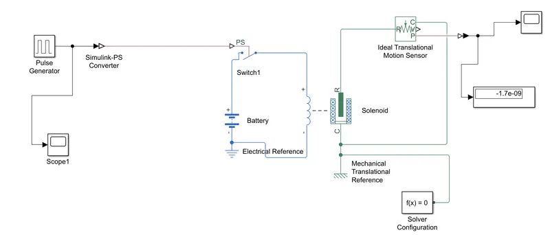
ANS-> The below blocks are used for creating the doorbell model
Requirements-> Pulse Generator, Simulink-PS converter, Switch, Battery, Solenoid, Electrical reference,
Mechanical reference, Ideal motion sensor, scope and display
Create the doorbell model using simulink
Pulse Generator-> The pulse generator block is used to create the square wave signals at regular intervals
Simulink-PS Converter-> It is used to convert the simulink signals to physical system
Switch-> The switch is used to pass the energy
Battery-> The battery is used to pass the current through the solenoid
Solenoid-> The solenoid means converting of electrical energy into electrical work
Ideal motion sensor-> The ideal motion sensor is used to connect the mechanical energy which is converted from
electrical energy using the solenoid and it will be connected to "R" in this sensor and the output will come from velocity and position and common reference
Electrical Reference-> The electrical reference is used as the ground which will be connected to negative value of the battery
Mechanical Reference-> The mechanical translational reference is used as the common reference in so many blocks
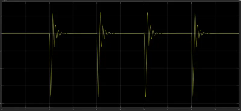
Scope -> It is used to get the pulse generator signals and to get the output of phase delay as 2 seconds
Solver Configuration->The Solver Configuration block specifies the solver parameters that your model needs before you can begin simulation
First we need to give the pulse generator as input to the switch. In pulse generator the phase delay must be given to the 2seconds as the after that when the switch is closed then the current passes through the battery to solenoid . The solenoid converts the electrical energy into mechanical work. The negative direction of the battery need to be connected to the electrical reference. The common ports of all the blocks will be connected to meachanical tranlational reference. The mechanical energy which is coming out from solenoid it need to be connected to the ideal motion sensor. The motion sensor will be converted the energy into the output using the velocity or position in the motion sensor . The scope will be used to take the input and will get the output in a graph model for a clear understanding
2)Thermistor->
The thermistor is also a type of resistor which will be used to get the temperature values accordingly
Due to the electrical resistance the thermistor value will be known. All the resistors can give the temperature values but the thermistor is made noe type of a material which will be used to get the temperature values. The thermistor will not be used in too hot or cold climatic conditions
There are mainly two types of thermistors
1.Negative coefficient thermistor
2.Positive coefficient thermistor
The main relation between these two types of thermistors is the negative coefficient thermistor will decrease its electrical resistance value when temperature increases. The positive coefficient thermistor will increase its electrical resistance value when temperature increases
The main aim of the challenge is to get the temperature values using thermistor given in the question
Requirements:-
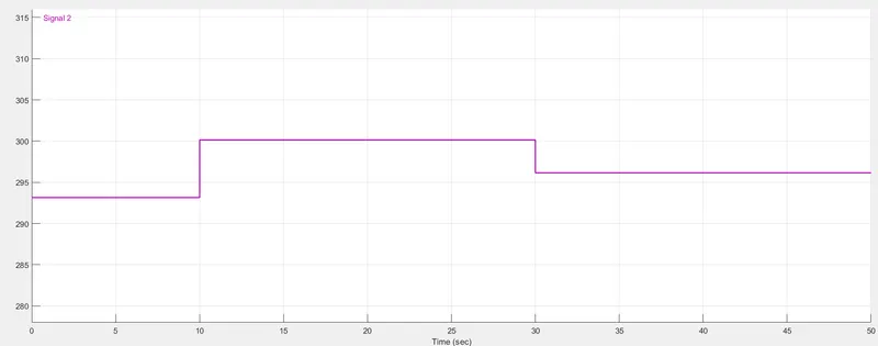
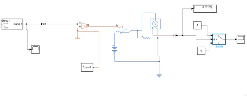
Signal Builder-> It is used to give the input signals as in a graph model
Simulink-PS Converter-> It is used to the simulink to physical system
Controlled temperature source-> It is a ideal source thermal energy which is powerful enough to maintain the differences of the temperature according to the heat flow consumed by system
In controlled temperature source there will be three ports the S,A and B . The S port is connected to the input and the A port will be connected to the thermal reference and B port is the one which will be getting the input from S port and also be connected to the thermistor
Thermistor-> It is a type of resistor which is used to get the temperature values
Battery-> It is used to pass the current through the battery and the negative indication of the battery is connected to electrical refernce
Voltage Sensor-> It is used to calculate the voltage flow passing through it the resistor will be connected to it. The voltage sensor and resistor positive to be connected to positive and negative should be connected negative
Switch -> The switch has 3 ports A,B,C the B port is the main port which is connected to the output signal of voltage sensor
The A and B ports are connected to the constant blocks. The A port will be considered when the B port is satisfies the given criteria which will be given in signal builder other wise B port will be considered
Scope-> The scope is used get the output either in a linear or pulse graph according to the input which we have given
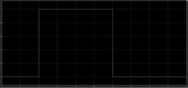
In the above given graph the situation which given in question is satisfied as the graph starts from 0 to 10th second from the 10th second the graph starts and continues till to the 25th second after the 25th second again the input in signal builder had given the 23 degrees so it has came to zero level again.
Signal Builder Input: