Week -2
Challenge 1: Make a Simulink model of Doorbell using solenoid block with the following details:
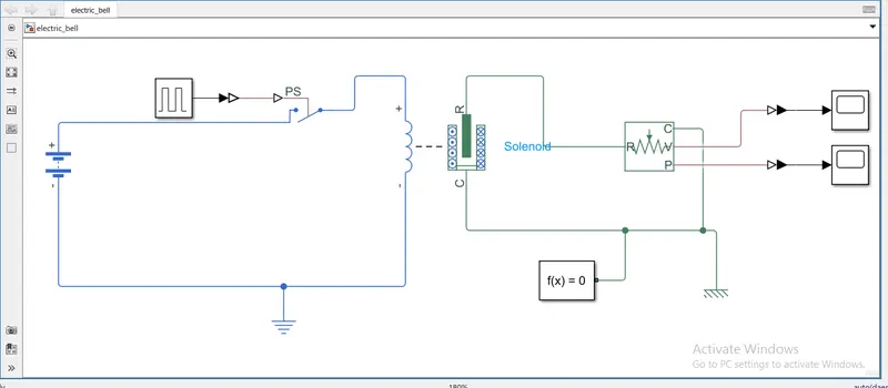
Blocks used: Battery, pulse generator, simulink to ps converter, switch, solenoid, ideal translational motion sensor, mechanical translational reference, electrical reference, solver configuration and scope.
Connecting the blocks:
Connect the +ve of battery to +ve of switch and -ve of switch block to the +ve terminal of the solenoid and -ve of solenoid to the negative of battery.
pulse generator block is used to provide input to the switch to remain open or closed.
so connect the output of pulse generator to the ps port of the switch.
by double clicking on the pulse generator we can input our values like period is 4 sec and since the switch remains open for 2 sec pulse width is 50% and click ok.
connect electrical reference in between solenoid and battery.
connect R port of solenoid to the r port of ideal translational motion sensor and c port of solenoid to c port of ideal translational motion sensor.
connect solver configuration and mechanical translational ref block to the circuit.
connect scope to the v and p ports of the ideal translational motion sensor.
set the simulation time to 10 secs and run the simulation.
below is the image of block sets for an electric bell.
when we run the simulation for 10 secs.
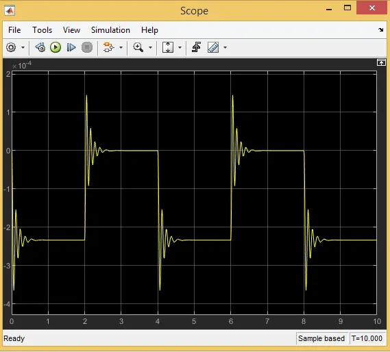
we can see in the image that for every 2 secs the position of the solenoid changes which represents that the bell is it at an interval of 2 secs.
Google drive link for electric bell challenge: https://drive.google.com/file/d/1VuL_mPQ7nK2GhD7qHWJNSF-wASBuDJqw/view?usp=sharing
Challenge 2: Use a thermistor to sense the temperature of a heater & turn on or turn off the fan as per the below conditions:
Temperature source: 20 °C from 0 to 10 seconds, 27 °C from 10 to 30 seconds, 23 °C from 30 to 50 seconds
Fan conditions: ON if the temperature above 25 °C, OFF otherwise.
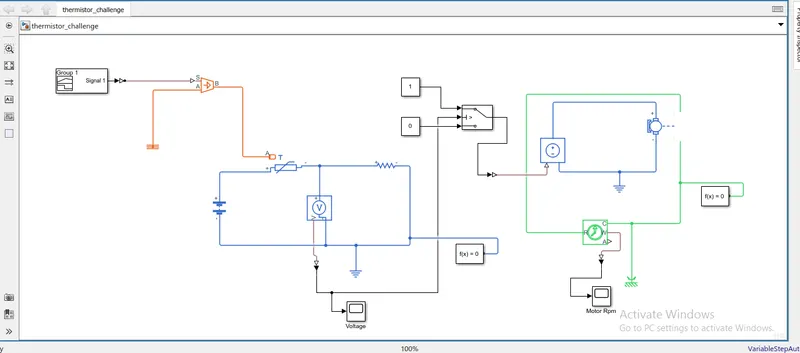
This can be solved by dividing into three categories circuit of simlink blocks.
Blocks used:
Category 1: in this we build a circuit to provide the temperature input to the thermistor by using the following blocks: signal builder, controlled temperature source, thermal reference, thermistor.
Category 2: in this we take the temperature input from the temperature source to the thermistor and connect a resistance of 1 ohm inseries and take a note of voltage across the resistor at the particular temperature. the following blocks are used: BATTERY, resistor, voltage sensor, electrical reference, solver configuration, scope, ps-simulink converter and simulink to ps converter.
Category 3: in this we take the input from the voltage sensor and by using the switch block and configuring it we run the motor as per the given conditions and the blocks used for the same is as follows: controlled voltage source, dc motor, ideal rotaional motion sensor, electrical reference, solver configuration, scope, ps-simulink converter and simulink to ps converter.
Step-2: Connecting the blocks.
category-1:
connect the output of the signal builder block to s-port of controlled temperature source block.
Connect the output of thermal reference block to A-port of controlled temperature source block.
Connect the b-port of controlled temperature source block to the A-port of thermistor.
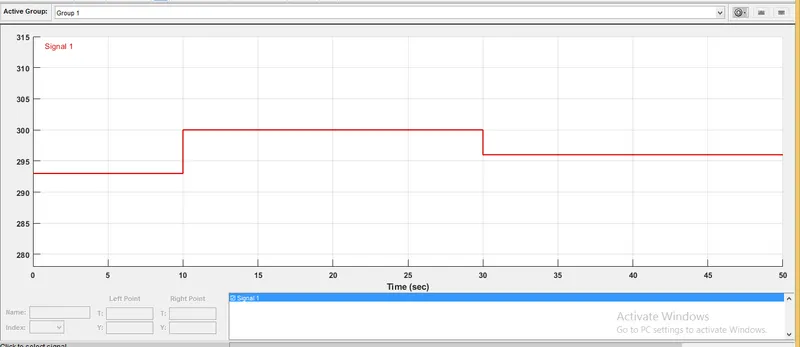
to configure the signal builder block:
In this block temp is in kelvin scale.
set x axis as time from 0 to 50 secs.
y axis limits up to 310 k.
as given in the problem set 293 K for 0 to 10 secs, 300 K from 10 to 30 secs, 296 K 30 to 50 secs.
category-2:
connect the positive terminal of the battery to the positive of thermistor and the negative of thermistor to the positive of resistor, the resistor negative to the negative battery terminal.
connect voltage sensor in parallel to the resistor and a electric ref to the circuit also a solver config block.
category-3:
connect the + and - ports of controlled voltage source block to the + and- port of electric motor respectively.
connect an electrical ref to the circuit.
connect r and c port of motor to the r and c port of Ideal Rotational Motion Sensor respectively.
connect mech rot ref and solver config bolck in between c ports.
connect scope to the w port of Ideal Rotational Motion Sensor to view the rotation of the motor.
connect the output of the switch to the v port of controlled voltage source.
connect constant block to the other two ports of the switch.
connect the v port of the voltage sensor to the centre port of the switch which will set the threshold voltage for the switch to remain closed.
since the motor remains on for temp>25 deg we determine the voltage output at 25 deg and set the same as threshold value of the switch which is known to be 0.012 in this case.
now run the simulation for 50 secs.
Google drive link for thermistor challenge: https://drive.google.com/file/d/1AwD5ZW-DmGPRhllKG2J07w1KMYwivXBx/view?usp=sharing
simulation results:
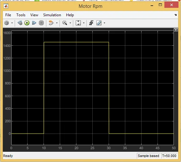
from the fig we can see that the motor remains on between 10 to 30 ssecs when the temp> 30 deg.