Week -2
Que1 ans)
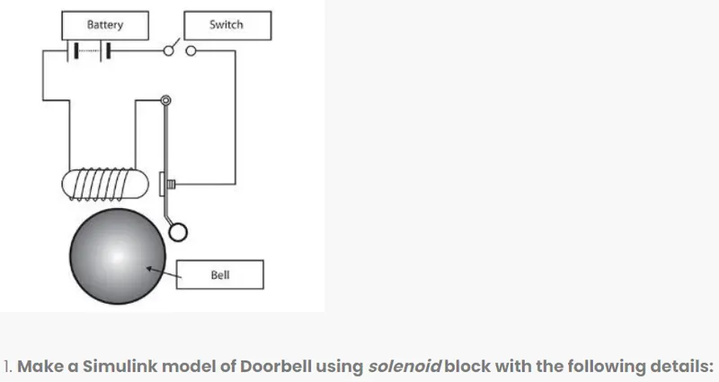
In the above arrangement, when the switch is closed the electromagnet receives electrical power from the battery and pulls the metal arm to hit the bell producing sound.
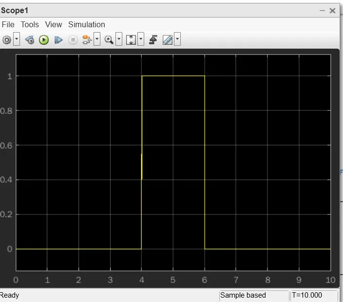
Create a situation where the switch is closed for 2 seconds and then released. Observe the physical movement of the plunger.
Principle:
Solenoid is a electromagnet which is convert Electrical energy into Mechanical energy.When current is applied, magnetic field is generated in the coil which displaces the stell arem present inside it. The length of this movement called stroke & forced of stroke measured in Newton(N).
Simulink model of doorbell using solenoid block:
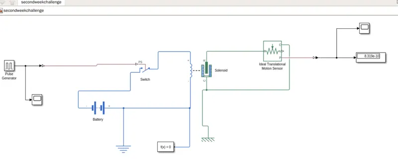
List of block used in above model:
1.Pulse generator
2.PS-simulink & Simulink PS-converter
3.Scope
4.Switch
5.Battery
6.Solenoid
7.Ideal Translated Motion sensor
8.Solver Configuration
9.Electrical & Mechanical Referance
Description of Block:
Input:
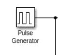
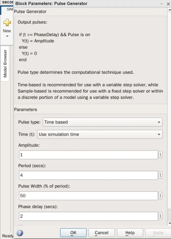
1.Pulse Generator- This is an analog input that has amplitude and frequency with which the input is transmitted.
2.PS-simulink & Simulink PS-converter-
This are the basically converter from physical system to simulink signal and vice-versa.
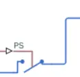
3.Switch-
This device the completes the electric circuits for current flow and can be controllrd manually or automatical depend on type of switch required.
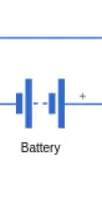
4.Battery:
This is device a negative and positive terminal for the electric circuit to be completed for electric flow.
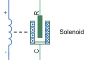
5.Solenoid-
This is an Electromagnetic device that is represent as a block here.
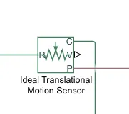
6.Ideal Translated Motion sensor-
It is the type of sensor which provided or velocity input for the system to generate output.
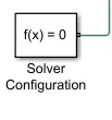
7.Solver Configuration-
It is act as a complete equation for where f(x)=0 where we find the value of x & generate the output.
8.Electrical & Mechanical Referance-
This is referance block with which system has ground source as a base.
Output:
1.Scope1 :
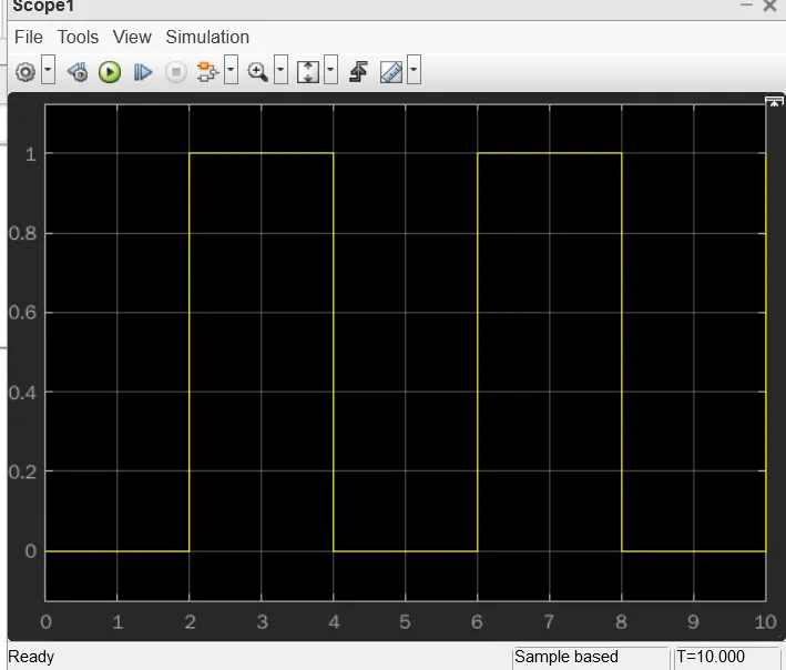
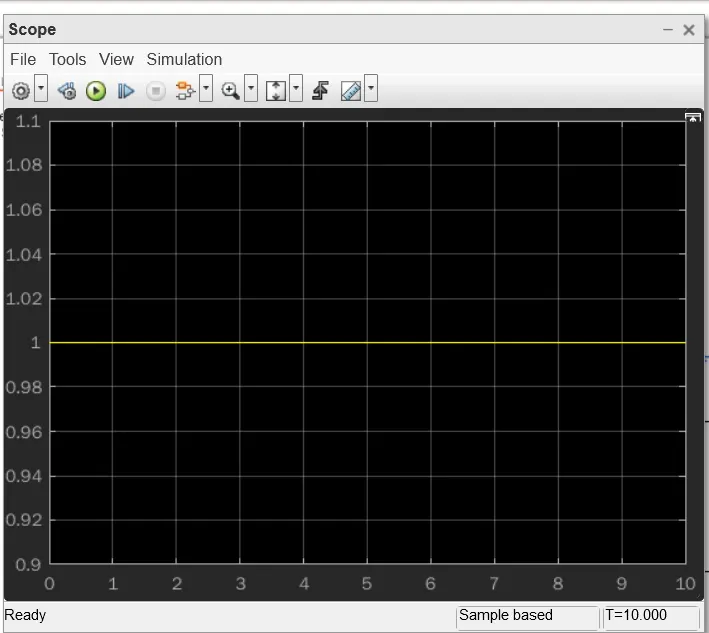
2.Scope2:
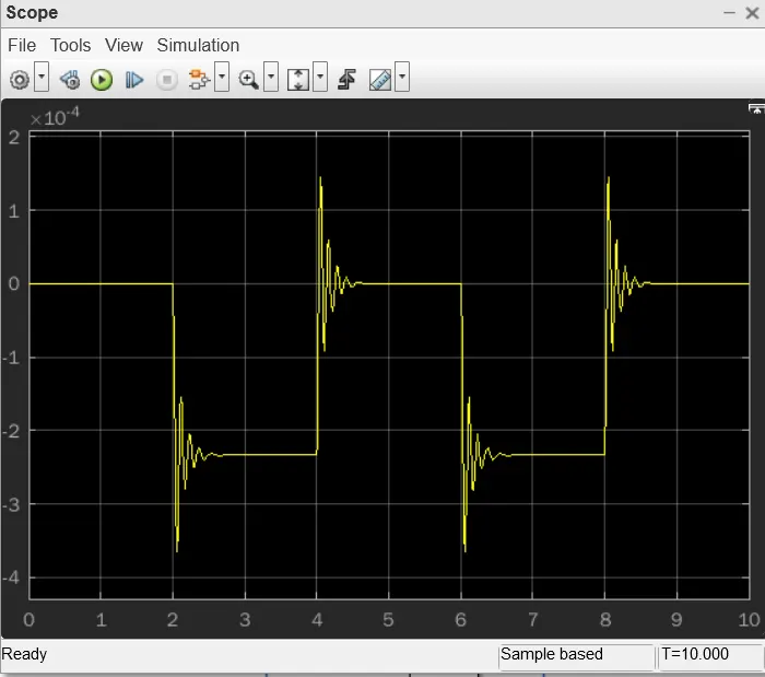
Que2 ans):Use a thermistor to sense the temperature of a heater & turn on or turn off the fan as per the below conditions:
we going to use the same procedure as above to simulate a thermistor to sense the temperature of a heater.
Thermistor: thermal resistor is defined as a type of resistor whose electrical resistance varies with changes in temperature. Although all resistor's resistance will fluctuate slightly with temperature, a thermistor is particularly sensitive to temperature changes. Thermistors act as a passive component in a circuit. They are an accurate, cheap, and robust way to measure temperature. While thermistors do not work well in extremely hot or cold temperatures, they are the sensor of choice for many different applications. Following is the Simulink block assembly for Thermistor based heater. And with condition follows here as:
1.0-10 sec temperature 293
2.10-30 secs temperature 300
3.30-50 secs temperature 296
Simulink model design :
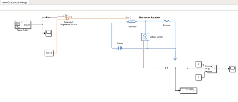
1.Signal Builder-
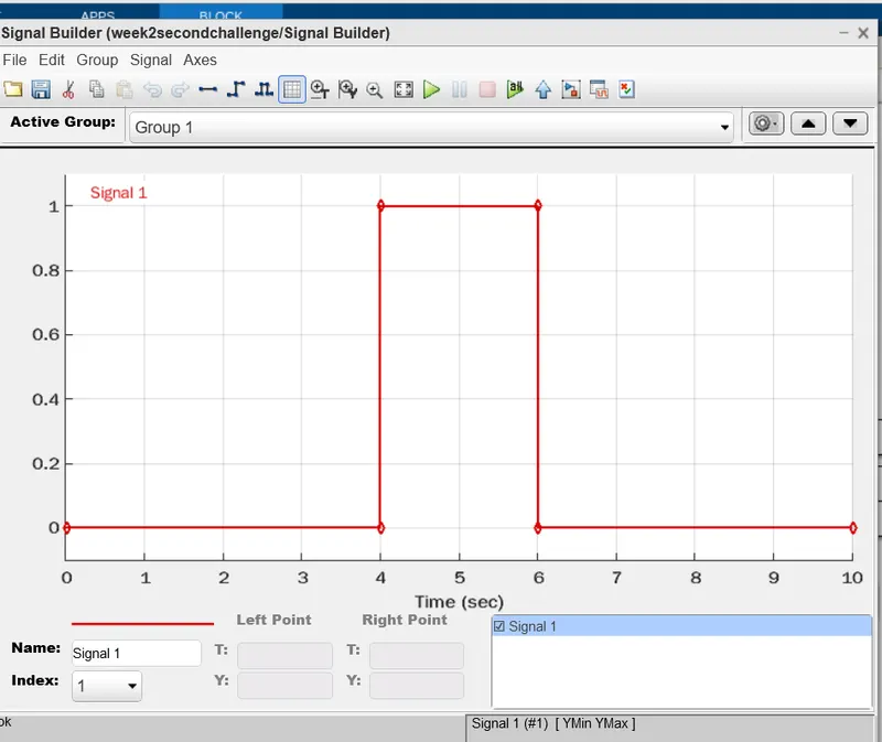
The signal builder block allow you to creat interchangeble group of piecewise linear signal source and used in model.
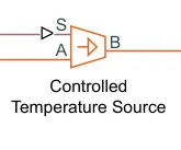
2.Controlled temerature source-
This block represent an ideal source of thermal energy that is power full enough to maintain specified temperature difference across the source regardless of the heat flow consume by the system.
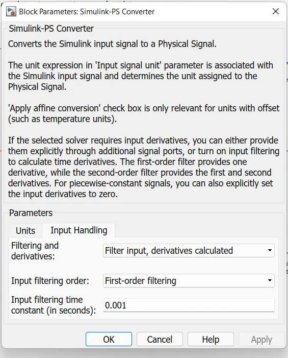
3.Simulink-PS converter-
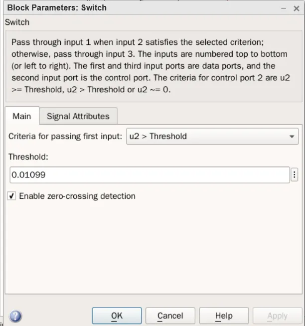
4.Switch-
5.Scope-