Week -2
1.
Door Bell Model
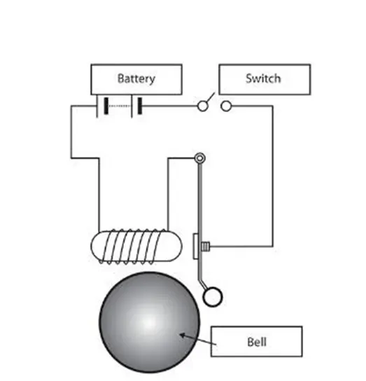
Simulink Model: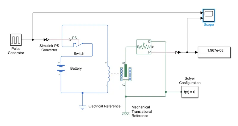
The above Simulink model realizes the working of a Door Bell using a solenoid block.
In the above model we use
PS Switch:
Single-pole double-throw switch is controlled by an external physical signal. If the external physical signal PS is greater than the threshold, then the switch is closed, otherwise, the switch is open.
Pulse generator:
A pulse generator is either an electronic circuit or a piece of electronic test equipment used to generate rectangular pulses. Pulse generators are used primarily for working with digital circuits, related function generators are used primarily for analog circuits. In the above circuit, it is used to provide a pulse to regulate the switch having a time period of 240 sec.
Solenoid:
It is an electromagnetic device that produces a uniform magnetic field. The Force of the magnetic field is determined by the number of turns or the current passing through the coil. In this Simscape model, Plunger is initially at position X, When the inductor part is charged, a Magnetic field is produced and Plunger moves. A damper and Spring are attached in this model to have the desired behavior.
Translational Motion Sensor:
The sensor is ideal since it does not account for inertia, friction, delays, energy consumption, and so on. This sensor is responsible for detecting a physical movement in the system and measuring the change.
Solver Configuration:
The Solver Configuration block specifies the solver parameters that your model needs before you can begin the simulation.
Simulation
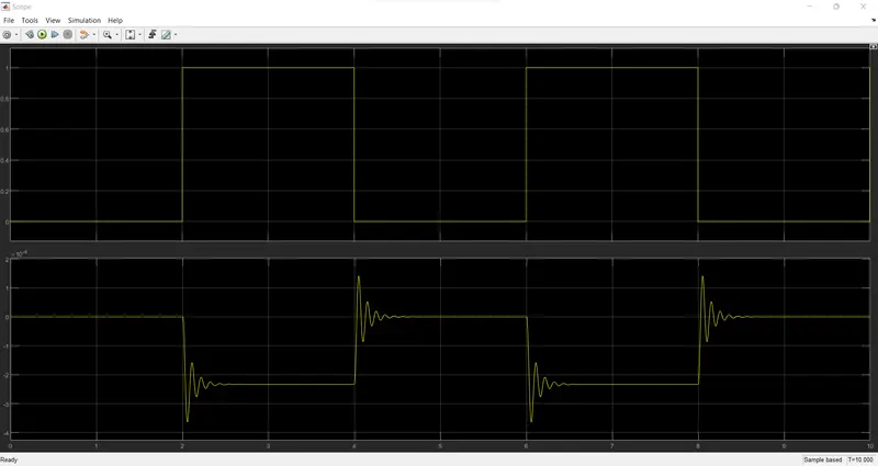
From the above graph, we could observe that whenever the circuit is ON by providing a pulse which is in ON state for 2 seconds and OFF for next two seconds. We can see a deflection in the output waveform, which denotes the change in position of a plunger.
2.
Thermistor - Fan Controller
Simulink Model:
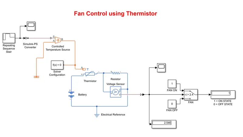
The above model is the representation of a Temperature Fan controller using a Thermistor. This model includes the following:
Thermistor:
The thermistor works on the simple principle of change in resistance due to a change in temperature. When the ambient temperature changes the thermistor starts self-heating its elements. its resistance value is changed with respect to this change in temperature. This change depends on the type of thermistor used.


Repeating Sequence Stair
The Repeating Sequence Stair block outputs and repeats a stair sequence that you specify with the Vector of output values parameter.
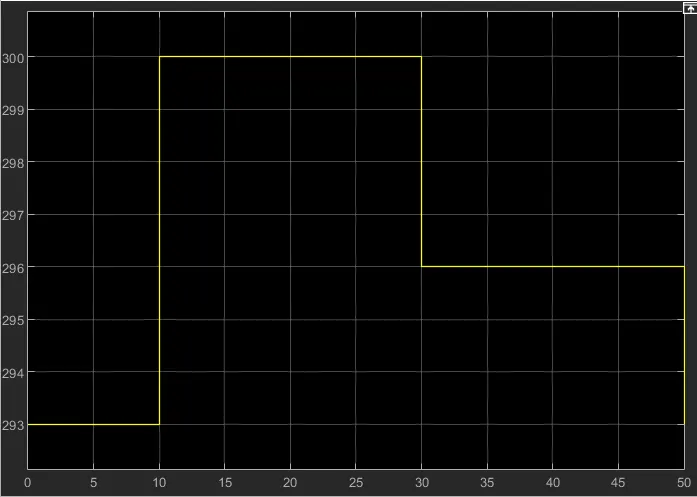
In the model, we used a repeating sequence stair, through which the temperature inputs are given in K. It is configured to
a) 20°C - 0 second to 10 seconds
b) 27°C - 10 seconds to 30 seconds
c) 25°C - 30 seconds to 50 seconds
As per the inputs the input temperature waveforms are shown below:
Simulink - PS Converter:
The Simulink-PS Converter block converts the input Simulink signal into a physical signal. But using it as a Filter Input. This input is given to a Simulink - PS Converter. And then to a Controlled Temperature Sensor. This sensor senses the temperature and then gives it to the input of the Thermistor. We use a battery as a voltage source, then the current flows through the thermistor. When the temperature increases or crosses the threshold temperature, the thermistor conducts and we used a voltage sensor to measure the voltage across the resistor, which is connected in series with the thermistor. Using the voltage sensor, we get the output voltages. And the output waveform is shown below:
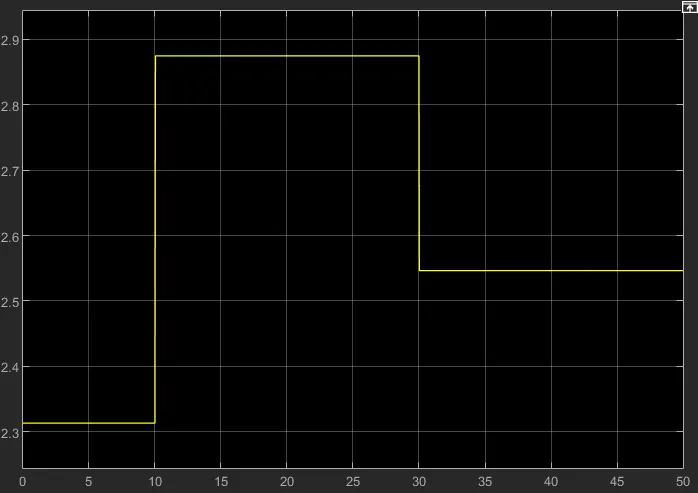
By comparing both input and output graphs, at 25°C (298K) the output voltage is around 2.4 Volts. To ON and OFF the fan we used a switch with input 1 - ON STATE and 0 - OFF STATE. And with threshold > 2.4 V, ON or OFF condition is used. By running the simulation, at 20 sec the temperature is 27°C - So the Fan displays 1 - ON STATE. At 10 sec the the temperature is 20°C - So the Fan displays a 0 - OFF STATE. So we have demonstrated a Fan ON and OFF state using a thermistor.