Week -2
Answer 1:
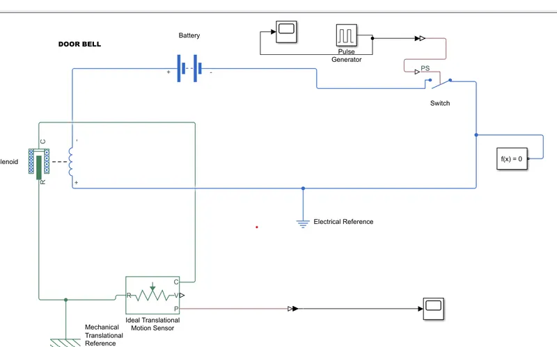
This is my Doorbell Simulink Diagram here are blocks i have used,
Explanation:
In this diagram Solenoid block is connected to positive side of Battery and Switch to get complete Circuit and port R is connected to ideal Translation to observe the movement of pluger and port c is connected to mechanical Reference.
Scope is connected to ideal translation sensor to get output.PS simulink is used to convert physical to simulink signal.
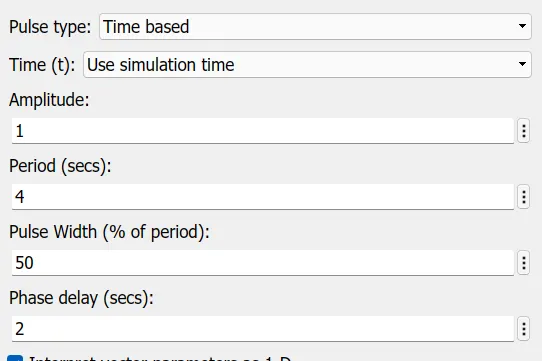
Pulse Generator is used to create pulse in regular intervals.Block waveform parameters are Amplitude,pluse,width,period and phase delay to determine the shape of ouput wave.
Reslut:
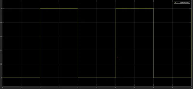
Time period given 2 second to the pulse generator to open and close the switch.When the switch is closed Solenoid receive electrical power from the battery and pluger move from R to C to hit the bell and sound is produced.
Answer2:
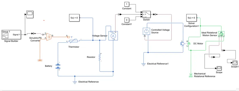
Here I use thermistor to sense temperature of a heater and turn on/off the fan.
THERMISTOR: A thermistor is a resistance thermometer or a resistor whose resistance is dependent on temperature.
Condition:
Here input given to singal builder as per condition Temperature 0 to 10 second 293K fan is off, 10 TO 30 second 300k fan is on and 30 to 50second temperature is below 25 degree celsius fan is off.
Explanation:
In this simulation Simulink-PS that convert Simulink signal into Phyiscal Singal given to Controlled Temperature Source block which repersent ideal source of thermal energy that is powerful enough to maintain specific temperature difference across the regardless of the heat flow consumed by the system.
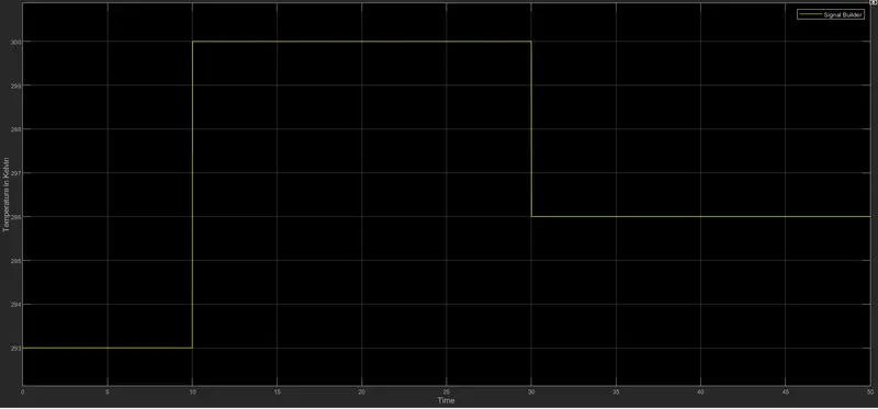
The Singal is pass to Thermistor which is connected to battery. Then the Voltage Sensor is connected to Resistor which is used to measure the voltage as a thersoled value for the condition of the our circuit.
As per Fan condition that ON if the temperature is above 25 deegre celsius, OFF otherwise. I use Switch and provide a thersiold value. If the signal is greater than thersold value then tha fan is ON otherwise it will be OFF.
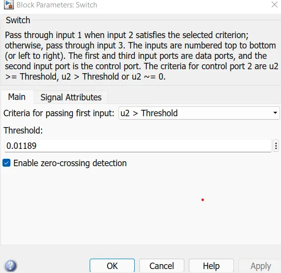
Then the signal is connected to controlled Voltage source which is connected to positive and negative terminal of DC motor which represent Fan this ciruit was grounded to electrical reference.
In dc motor C block is connected to Mechanical rotational reference and in order to calculate the angular velocity of the motor, and its R port was connected to R port of ideal rotational sensor.in case this also connected to mechanical rotational reference.
The output was taken by W port which measure angular velocity and then it connected to Slover configuration as each circuit connected to one. The singal was converted into simulink and then displayed into Scope
Simulation time is changed into 50sec to capture all the event.
Ouput:
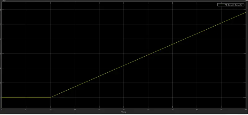
Conclusion:
When the DC motor turned on and off when the temperature difference was notice with thermistor and the switch and the RPM motor was observed by scope.