Week -2
- Make a Simulink model of Doorbell using solenoid block with the following details:
In the above arrangement, when the switch is closed the electromagnet receives electrical power from the battery and pulls the metal arm to hit the bell producing sound.
Create a situation where the switch is closed for 2 seconds and then released. Observe the physical movement of the plunger.
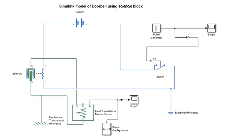
Ans - In formulation of simulink model of doorbell using solenoid block, following blocks are used
a) The Pulse generator is used for generating pulse at regular intervals.This block's waveform parameters such as amplitude,period,pulse width & phase delay determine the shape of waveform generated.
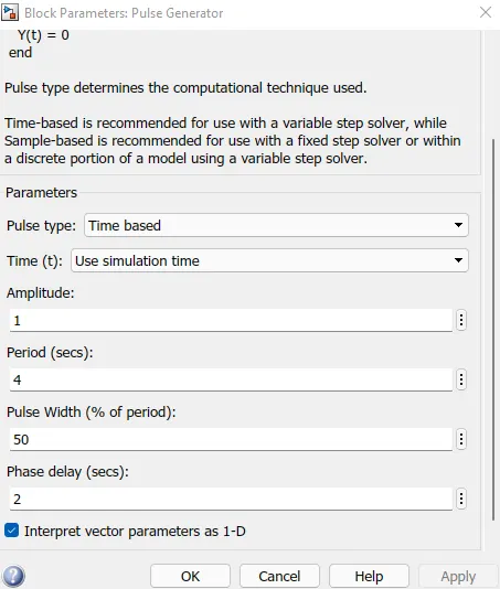
The waveform generated is as shown below

b) The switch block used is controlled by external physical signal generated by pulse generator.If the external signal is greater than threshold then the switch will be close or ON otherwise it will be open or OFF.
c) One end of the switch is connected to negativ terminal of battery & the other end is connected to electrical reference.
d)The solenoid block is connected to positive terminal of battery at one end and switch at other end to complete the electrical circuit of this model.
e)The ideal transational motion sensor is connected with plunger of solenoid and we recieve the position of plunger as an output. Scope is connected to ideal transational sensor to get the output.Below waveform shows the position of plunger.

f) Every physical network of this simscape model requires solver configuration setting information for simulation
g) PS-Simulink/Simulink-PS converter are used at desired places for connectivity of simuling blocks with physical signals
2. Use a thermistor to sense the temperature of a heater & turn on or turn off the fan as per the below conditions:
Temperature source: 20 °C from 0 to 10 seconds, 27 °C from 10 to 30 seconds, 23 °C from 30 to 50 seconds
Fan conditions: ON if the temperature above 25 °C, OFF otherwise
Ans: Blocks usedin model :
1. Signal builder block
2.controlled temperature source
3.Thermistor
4.Resistor
5.Voltage sensor
6.Battery
7.Switch
8.Lamp
9.Scope
10.Display
11.Simulink-PS converter
12.PS-Simulink converter
13.Solver configuration
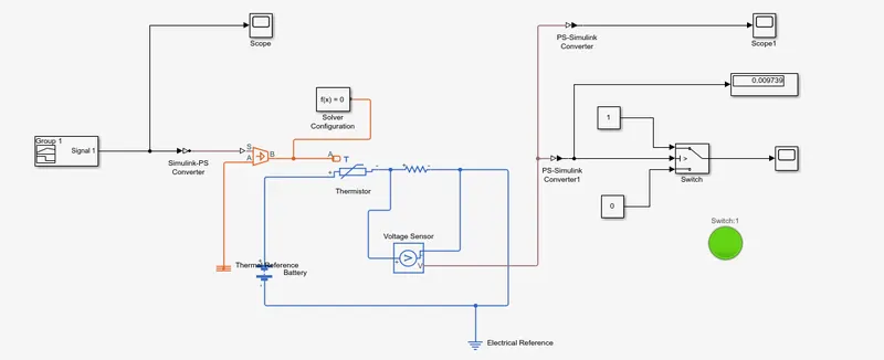
Model Explanation
A signal builder block is used to initiate the input to the thermistor through a controlled temperature source.The sample time is taken as 10 sec.The whole simulation time is taken as 50 sec.
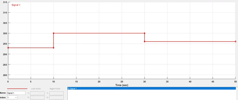
Battery & resistor is connected in thermistor circuit.A voltmeter is connected across the resistor to measure the voltage change during different temperature inputs.The resistance of the resistor can be set to any value but it should not change when the threshold value is achieved.The threshold temperature is given as 25 deg celsisus or 298 K and the corressponding voltage over the resistor is seen on display connected to voltage sensor. At this time the signal builder block provides on one value 298 K.The output voltage is connected to the switch which itself is connected to a lamp.The Lamp glows green when the threshold is achieved and above.