Week -2
- Make a Simulink model of Doorbell using solenoid block with the following details:
In the above arrangement, when the switch is closed the electromagnet receives electrical power from the battery and pulls the metal arm to hit the bell producing sound.
Create a situation where the switch is closed for 2 seconds and then released. Observe the physical movement of the plunger.
SOLUTION
DoorBell Simulink Diagram
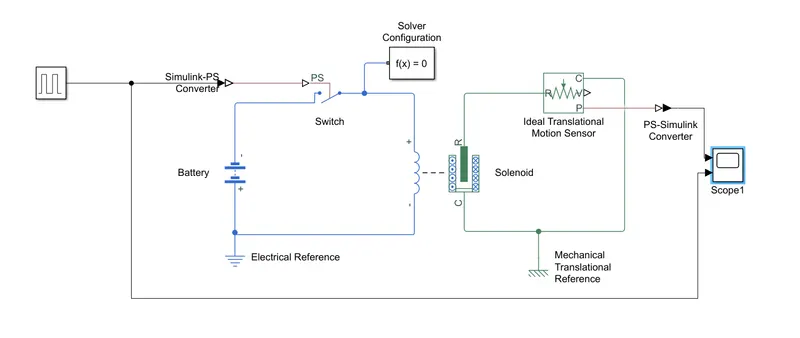
Simulink Model Explanation:
- The pulse generator is used to create square wave pulses at regular intervals.the block diagram wave form parameters amplitude ,pulse width,period and phasedelay,determine the shape of the output waveform.
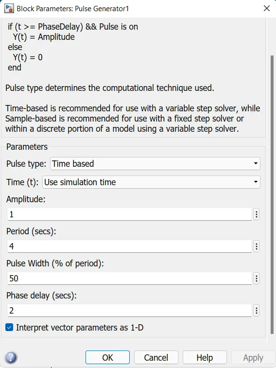
- The Switch block used is controlled by external physical signal is greater then the thresold parameter then the switch is closed,otherwise switch is open.
- The positive terminal of the switch is connected to switch and the negative terminal is connected to the electrical reference.
- The solenoid block is connected width switch and battery and we will get a complete electrical circuit. The port C is connected width mechanical reference.
- The ideal translational sensor is connected width solenoid block R to observe the movement of the plunger.
- Scope is connected width the ideal translational sensor to get the output.
- PS-Simulink converter is used to convert the physical signal to simulink signal.
- Solver configuration,each physical network represented by a connected simscape blocks requires solver setting information for simulation.
RESULT:
OUTPUt AND INPUT Waveforms:
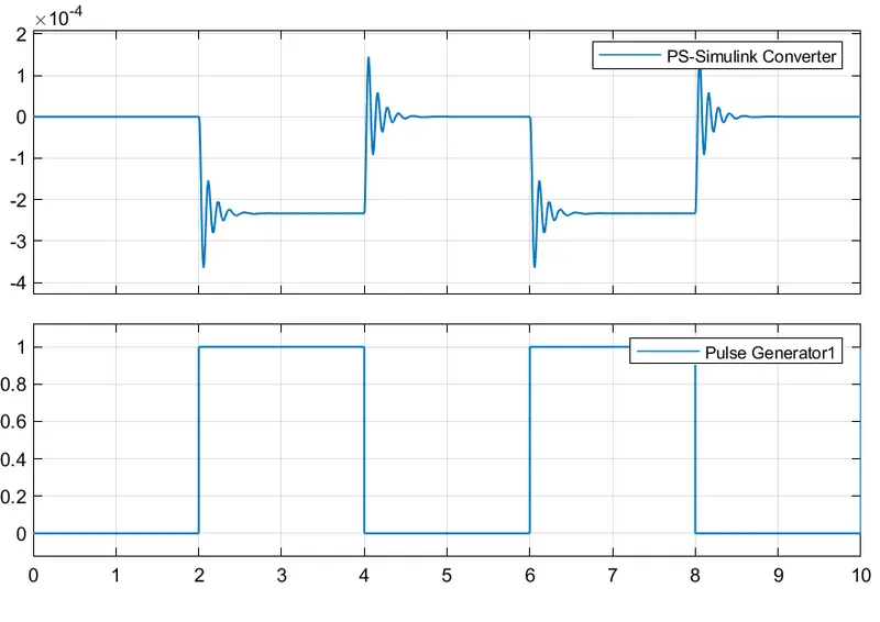
- Time period given is 2 seconds to the pulse generator to open and close the switch is closed the solenoid blocks receives electrical power from the battery and the plunger move from port R and C to hit the bell and produce sound.
2. Use a thermistor to sense the temperature of a heater & turn on or turn off the fan as per the below conditions:
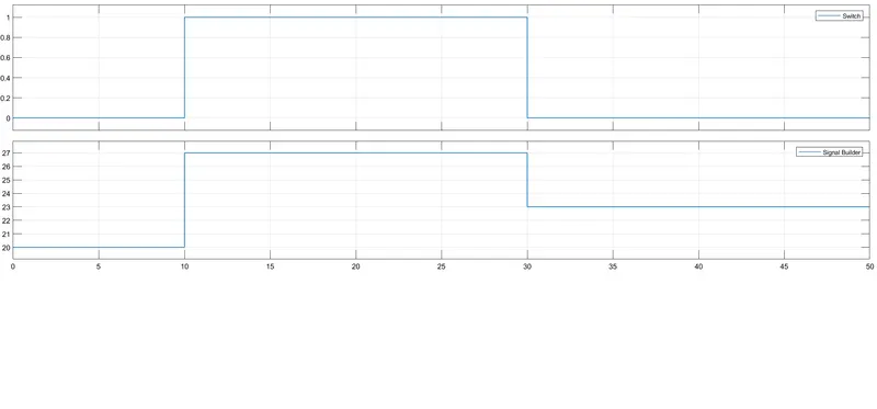
Temperature source: 20 °C from 0 to 10 seconds, 27 °C from 10 to 30 seconds, 23 °C from 30 to 50 seconds
Fan conditions: ON if the temperature above 25 °C, OFF otherwise
Solution:
Simulink Diagram
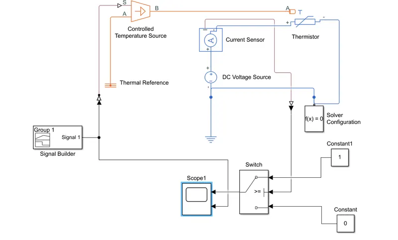
Simulink Model Explanation:
- Signal,Builder block is uded to input the values as per given conditions:
- At point,Time=0 seconds,Temperature=20 °C
- At point,Time=10 seconds,Temperature=20 °C
- At point,Time=10 seconds,Temperature=27 °C
- At point,Time=30 seconds,Temperature=27 °C
- At point,Time=30 seconds,Temperature=23 °C
- At point,Time=50 seconds,Temperature=23 °C
find threshold value,
- Fan conditions: ON if the temperature above 25 °C, OFF otherwise
- So First set the input 25 degree in signal builder then save and important to connect the output from current sensor - ps to simulink converter - scope to get the threshold value. i will attach the waveform.
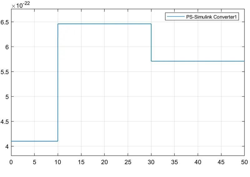
- so,threshold value is 5.72*10^-22.
- helce this condition when proved 25 degree C is fan ON otherwise OFF.
- Controlled temperature sourse represents an ideal source of thermal energy.that can maintain a controlleed temperature difference regardless of the heat flow rate.the temperature difference is set by the physical sigbal port S.A positive temperature difference causes the temperature at port B to be greater then the temperature at port A.
- Thermistor is a type resistor whose resistance is based upon temperature.
- The current sensor is used to convert the current measured between two points into a physical signal.
- Voltage source which represents 12v dc.
- Electrical refrence block is given.
- Solver configuretion ,Each physical network represent by a connected simscape blocks requires solver setting information for simulation.
RESULT:
From the above conditions ,all the values are evaluated.
- Fan conditions: ON if the temperature above 25 °C, OFF otherwise.