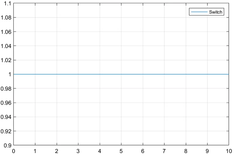
Week -2
Aim : Make a simulink model of Doorbell using solenoid block.
Report:
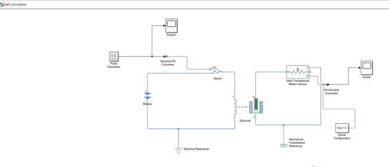
1.In simulink Model of door bell using solenoid block,we need a switch,solenoid,battery and a plunger. 2. Now first a 'solenoid block' is taken to represent a solenoid in the model, then to represent battery we have taken ' Battery block' from the library browser. Then this 'solenoid block' and 'battery block' are connected to each other via positive and negative terminals. 3. A switch block is placed between solenoid blocks and battery block and is connected with both blocks. Now for switch to operate we need to provide physical signal through 'simulink to ps converter' in the switch block.The provided physical signal should be greater than the thresholdof the switch, for switch being close, or else it will be open. 4.Now the whole battery switch and solenoid path is connected to an 'Electric referance block' which represents earthing of the circuit. this 'electric referance block' should be connected to the negative terminal of the battery block. 5. Then in the solenoid block R and C are two variable which represent plunger and fixed point respectively. Now the solenoid block 'R' is connected to 'R' of ideal traslation motion sensor block which senses the position of plunger in the solenoid block and gives the output. Now in the ' Ideal translation motion sensor block' the output are given as 'V' and 'P' which represents the velocity and position of the plunger, since we are interested in knowing the change in position of the plunger , so we need only results 'P' output. 6. Now 'C' in the ideal translation motion sensor block is connected to mechanical translation conserving ports, which means that the mechanical process starts from 'R' and end at 'C' and again it start at 'R' and the cycle goes on. 7. So 'C' in the ideal translation motion sensor block is connected to the Mechanical translation referance which represents fixed points. Similarly 'C' of the solenoid block is also connected to the same mechanical translation referance as fixed point for solenoid. 8. Since we need position of the plunger as output from ideal translation sensor block we have connected port 'P' to PS-simulink converter' where the physical value from port 'p' are converted into simulink value, and then this 'ps-simulink converter' is connected to 'scope block' which will generate a graph for change in position of plunger from port 'p' . 9. Now to provide a physical signal for operating the switch, we have used a 'Pulse generator block' which generates a continuous spuare pulse. 10. Each physical network represented by a connected simscape block diagram requires solver setting information for simulation 'the solver configuration block' specifies the solver parameters that your model before you can begin simulation.
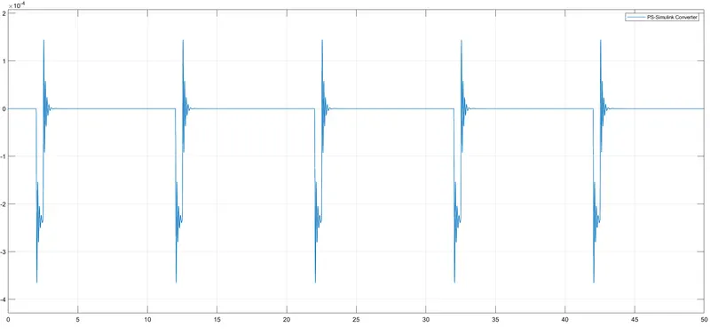
* The simulation was run for 50 seconds and result obtained is shown below.It can be observed that that at each 2 seconds bell was ringiing.
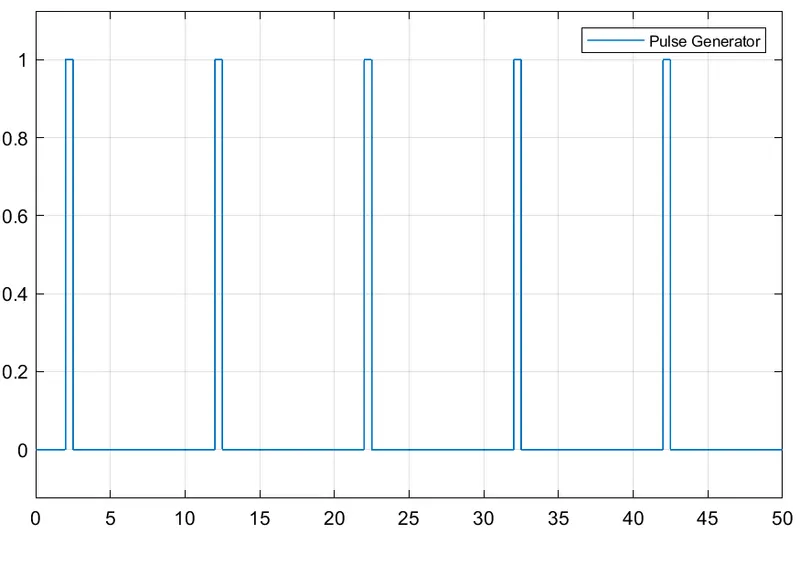
Above figure shows how the pulse is generated. Pulse generator gives signal to the switch in the form of square waves. This figure the x-axis represents the 'Time' and y-axis represents the 'amplitude' and the square wave is generated at every 2 sec.
*2) Use a thermistor to sense the temperature of a heater and turn on or off the fan as per conditions.
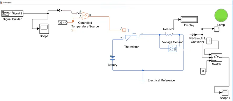
Report: *Started with the input signal gave the input signal with the help of Signal Builder as per the given condition. *The signal builder block is connected to 's' port of the controlled temperature source block with the help of a simulink-ps converter. the port 'B' of the controlled temperature source is connected to the 'A' port of thermister. * A scope is connected to the input signal then we make a thermister block and connect it to a battery as it is voltage source then we connect a resistor block and connect it to a voltage block to measure the voltage flowing through the resistor. * display block is connected to 'v' of the voltage sensor block with the help of a ps-simulink converter to display the output. *A conditional switch block with 2 constant blocks of value '0' and '1' is connected to the 'v' port of the voltage sensor. * As the threshold at 25 degree celcius and it given as threshold for switch. Switch block is connected to a scope to display the graph and the output of switch is connected to a lamp, the lamp glows green if the resistance across is less than the switch threshold meaning the fan is off, if the resistance across is higher than the switch threshold the lamp glows red meaning the fan is ON. Thermal referance and electrical referance is connected to the respective block.
INPUT SIGNAL:
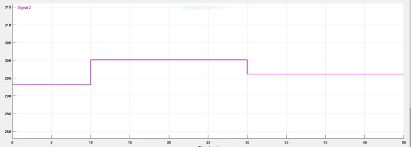
Temperature below 25 degree, fan is off
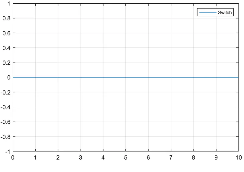
Output scope: 0 is the graph indicates the fan is off.
Temperature above 25 degree, fan is ON.
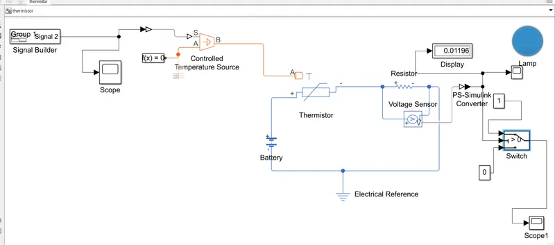
Output scope : 1 is the graph indicates the fan is ON.