Week -2
Project 1
- Here we are simulating a solenoid door bell which is connected to a voltage source, a battery in our case and the same is being turned on using a switch.
- As soon as the switch is turned on, a current runs through the solenoid/ door bell and a metal is struck.
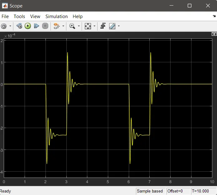
- In this project we are going to analyse the motion of the metal part.
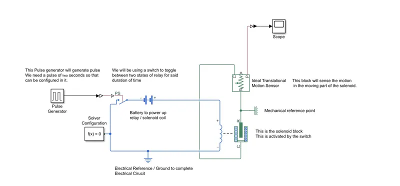
- We can see that there are the following parts in the arrangement
- Pulse Generator: Generate the switch ON signal for 2 Seconds as requested in the quesitonaire.
- Solver configuration: For equation formation while solving any simulation
- Battery: refering here to the voltage source which will switch on the solenoid
- Solenoid Block: The solenoid which is acting as a door bell here.
- Translational motion sensor: Sensor to understand the motion of the solenoid block when the switch is turned on and off.
- scope: to be able to see what the motion sensor detects in graphical form.
- various reference and converters
The output of the scope is going to be in the specific form:
Project 2:
Analysis of an effect of temperature on a negative thermal coefficient resistor. and Use a thermistor to sense the temperature of a heater & turn on or turn off the fan.
Temperature source: 20 °C from 0 to 10 seconds, 27 °C from 10 to 30 seconds, 23 °C from 30 to 50 secondsFan conditions: ON if the temperature above 25 °C, OFF
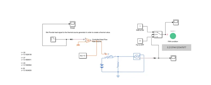
- In this project, we are using a signal generator, repetitive one to give heat signals to a heat source which is generating heat accordingly.
- That heat is being used to provide thermal signal to the NTC which in turn is being used in a voltage divider to analys the impact of change of resistance of the NTC while measuring a voltage across it using a voltage sense block.
- That voltage output is then being sent to a switch case where in a switch condition is being applied "if this then that" is happening in the switch, resulting to which, the fan is switching on( Depicted by the color of the LED ).
- Multiple values of the voltage divider resistance will give multiple voltage outputs. in my scenario, once the resistance value was fixed, i have written precise voltage values for precise temeprature inputs given on the left side of the Block.