Week -2
Question :- Make a Simulink model of Doorbell using solenoid block ?
Answer:-
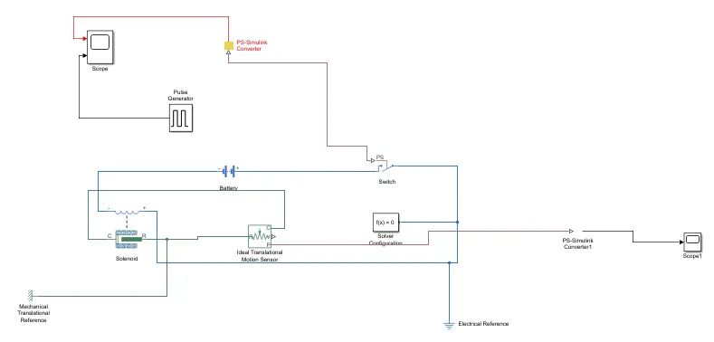
Simulink model explanation:-
1>Puls generator
2>Switch
3>Battery
4>Solenoid
5>Ideal Translational Motor Sensor
6>Mechanical Translational Referance
7>Electrical reference
8>Scope
As per given condition switch is closed for 2 seconds and then released.
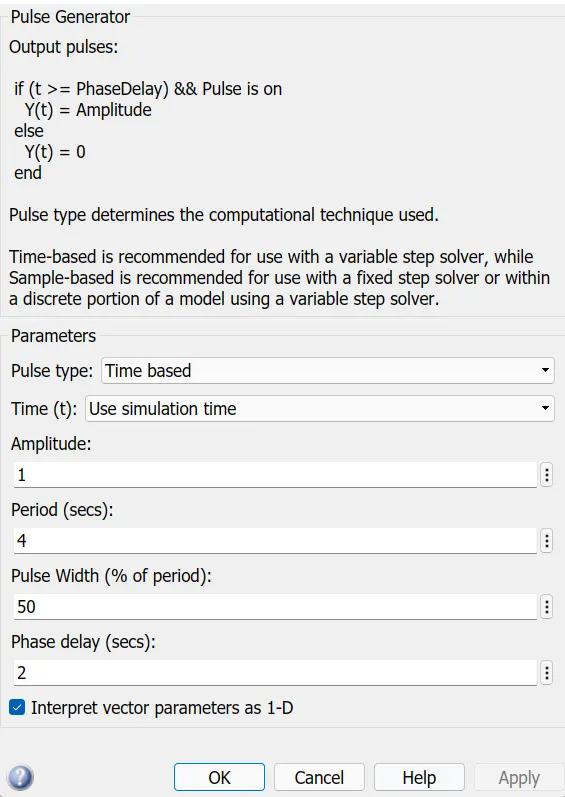
>The pulse generator is used to create square wave pulses at regular intervals . The block waveform parameters,Amplitude ,Pluse Width,Period and Phase delay,determine the shape of the output waveform.
>Simulink PS Convertor converts the simulink input signal to a physical signal.
>Switch controlled by an external physical signal.If the external PS is greater than the threshold,then the switch is closed,otherwise the switch is open.
>Battery provides the voltage to the system.
>Solenoid shows the position of the plunger with respect to the EMF induced,which depends on the initial position of the plunger.The spring constant is set to Zero.
>Mechanical and Electrical referance provides the reference point to the respective signals.
>Ideal Translational Motor Sensor is a device that converts an across variable measured between two mechanical translational nodes into a control signal proportional to velocity and position.
>Scope is used to view the characteristics of a property with respect to the time.
// SIIMULINK MODEL .
//RESULT OBTAINED FROM THE SIMULINK MODEL.
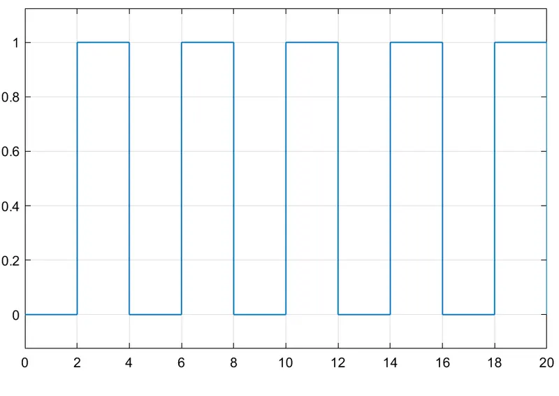
>> This is the result obtained for a time period for 20 seconds of the given simulation. For every interval of 2 seconds the switch is turned on and off hence such waveform is obtained .
>>Damping effect is observed because of the damping parameter which was set in solenoid block of 1N/(m/s)
>>The curve is positive as motion direction is set as 'Port R moves away from port C'
// CONCLUSION:-
>>Understanding of the changes in curve characteristic upon changing the solenoid parameters.
>>Understanding the principle if working of a Doorbell and its construction.
>>Analyzing the various Simulink library blocks.
2// Use a thermistor to sense the temperature of a heater & turn on or turn off the fan as per the below conditions?
Condition are :-
Temperature source: 20 °C from 0 to 10 seconds, 27 °C from 10 to 30 seconds, 23 °C from 30 to 50 seconds
Fan conditions: ON if the temperature above 25 °C, OFF otherwise?
Answer:-
>>Simulink Block used in model:-
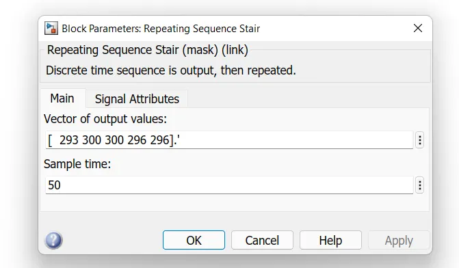
>Repeating Sequence Stair
>Controlled Temperature Source
>Thermister
>Resistor
>Voltage sensor
>Battery
>Switch
>Lamp
>Scope
>Display
>PS simulink converter
>Solver Configuration
//Simulink Model :-
// Simulink Model Explanation :-
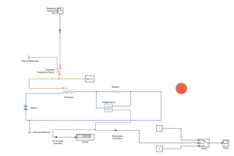
> Controlled Temperatur source represent an ideal source of thermal energy, that can maintain a controlled temperature difference regardless of the heat flow rate . The temperature difference is set by the physical signal port S. A positive temperature difference causes the temperature at port B to be greater than the temperature at port A.
> Thermistor is a type resistor whose resistance is based upon temperature.
> A linear resistor is used inorder to control the amount of current from the battery.
> The voltage sensor is used to convert the voltage measured between two points into a physical signal.
> Voltage source which represent DC or AC.
> Electrical refrence block is given.
> Thermal refrence block is given.
> Solver Configuration block is given. Each physical network represented by a connected simspace block requires solver setting information for simulation.